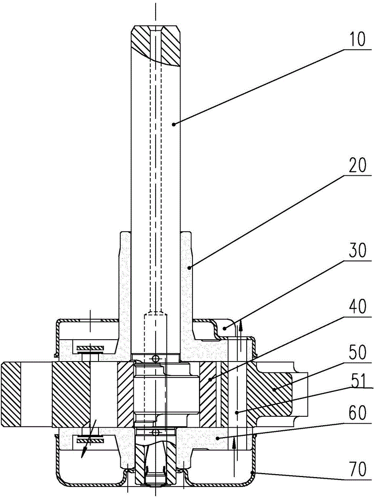
Pump body and compressor
A compressor and pump body technology, which is applied to liquid fuel engines, pump components, mechanical equipment, etc., can solve the problems of not being able to eliminate all of them, single silencing frequency, etc., and achieve the effect of simple structure and extended silencing range.
- Summary
- Abstract
- Description
- Claims
- Application Information
AI Technical Summary
Problems solved by technology
Method used
Image
Examples
Embodiment 1
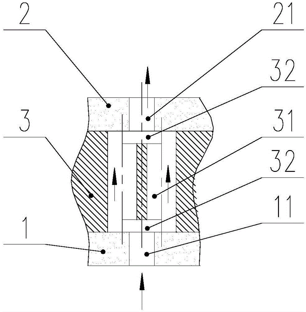
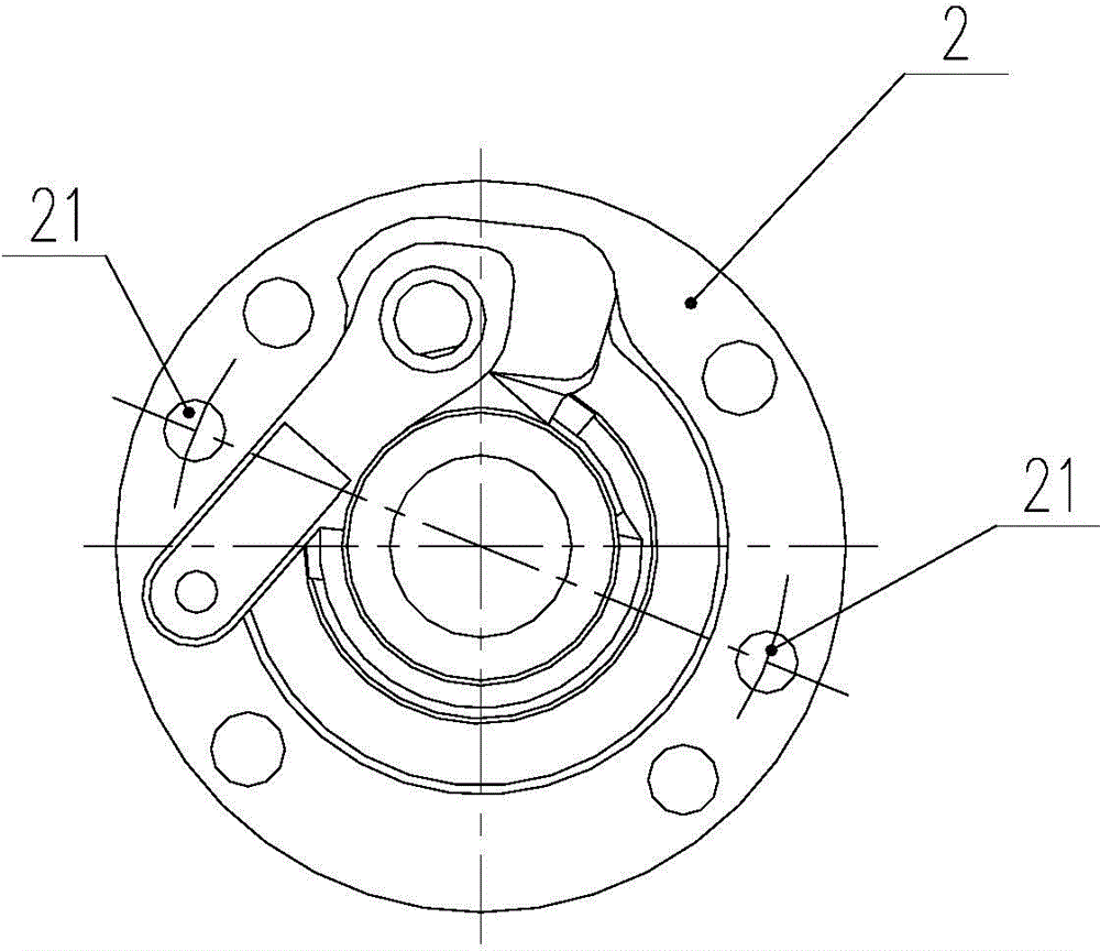
[0033] figure 2 It is a partial cross-sectional view of the pump body in Embodiment 1 of the present invention, showing the improved structural parts of the present invention. Other structures of the pump body are prior art and will not be repeated here. image 3 yes figure 2 The top view of the middle and upper flange, Figure 4 yes figure 2 Bottom view of the middle and lower flange, Figure 5 yes figure 2 Top view of the upper flange end of the middle cylinder, Figure 6 yes figure 2 Bottom view of the lower flange end of the middle cylinder. Such as Figure 2-6 As shown, the pump body includes an upper flange 2, a lower flange 1 and a cylinder 3 between the upper flange 2 and the lower flange 1, the lower flange 1 has an air inlet 11, and the upper flange 2 has an air inlet 11. Corresponding air outlets 21 are opened. On the cylinder 3, between the air inlet 11 and the air outlet 21, at least two intermediate passages 31 communicating with the air inlet 11 and...
Embodiment 2
[0038] Figure 7 It is a partial sectional view of the pump body of the second embodiment of the present invention. The difference between the second embodiment and the first embodiment is that the cross-sectional areas of the two middle channels 31 are different, that is, they form a pair of double-pipe noise-absorbing channels with different expansion ratios, so that the noise reduction of two frequencies can be realized. In the case of setting more intermediate channels, multiple frequencies of noise reduction can be realized.
Embodiment 3
[0040] Figure 8 It is a partial sectional view of the pump body of the third embodiment of the present invention. Such as Figure 8 As shown, the pump body includes an upper flange 2, a lower flange 1, and a first cylinder 6 and a second cylinder 4 located between the upper flange 2 and the lower flange 1, and between the first cylinder 6 and the second cylinder 4 A partition 5 is provided, an air inlet 11 is opened on the lower flange 1, a corresponding air outlet 21 is opened on the upper flange 2, and a partition channel 51 connecting the air inlet 11 and the air outlet 21 is opened on the partition 5 , on the first cylinder 6, between the gas outlet 21 and the partition channel 51, at least two upper intermediate passages 61 communicating with the gas outlet 21 and the partition channel 51 are set, and on the second cylinder 4, between the inlet Between the gas port 11 and the partition channel 51 , at least two lower middle channels 41 communicating with the gas inlet ...
PUM
 Abstract
Description
Claims
Application Information
 - R&D
- Intellectual Property
- Life Sciences
- Materials
- Tech Scout
- Unparalleled Data Quality
- Higher Quality Content
- 60% Fewer Hallucinations
Browse by: Latest US Patents, China's latest patents, Technical Efficacy Thesaurus, Application Domain, Technology Topic, Popular Technical Reports.
© 2025 PatSnap. All rights reserved.Legal|Privacy policy|Modern Slavery Act Transparency Statement|Sitemap|About US| Contact US: help@patsnap.com


