Control valve integrated with functions of pressure reducing, pressure maintaining and separating and application thereof

A technology for control valves and main control valves, applied in the direction of functional valve types, lift valves, balance valves, etc., can solve the problems of uncontrollable, high cost, large pressure difference, etc., to save resources and costs, facilitate installation and commissioning, and occupy small space effect

Active Publication Date: 2014-08-13
上海成峰流体设备有限公司
View PDF6 Cites 2 Cited by
  • Summary
  • Abstract
  • Description
  • Claims
  • Application Information

AI Technical Summary

Problems solved by technology

From the structural principle of the pressure reducing valve, it can be seen that the pressure reducing valve can only control the maximum pressure of the return water in the high area to discharge to the main return water pipe network, but cannot guarantee that the return water pipe in the high area will not produce negative pressure and empty
If the return pipe is emptied, it will produce high-level cold and low-heat and water vibration sound, and it will also corrode the high-level piping system and cannot empty the air in the pipeline
The isolator works by increasing the pipe loss. It can only reduce its dynamic pressure, and it cannot guarantee that the return pipe in the high area will not generate negative pressure.
If an open return tank is installed in the return water system in the high area, the water tank will occupy a large area, the heat loss will be large, the cost will be high, and oxygen corrosion will be increased at the same time
If a pressure relief valve is installed in front of the pressure reducing valve, although it is feasible in principle, both the pressure relief valve and the pressure reducing valve are controlled by pressure difference. A pressure reducing valve and a relief valve are connected in series on a pipeline. The pressure valve requires a large pressure difference. If the pressure difference is too small, it will affect the control sensitivity or cannot be controlled.
Especially when the backwater pressure in the high area is not much different from the municipal requirements, it cannot work, so now the direct heating equipment basically relies on a pressure reducing valve to work, although it can solve the problem that the backwater will not exceed pressure, but cannot control the negative pressure generated by the return pipe in the high area and the stability of heating

Method used


Image

  • Control valve integrated with functions of pressure reducing, pressure maintaining and separating and application thereof

Examples


Embodiment Construction

[0019] The technical solution of the present invention will be further described in detail below in conjunction with the embodiments and the accompanying drawings.

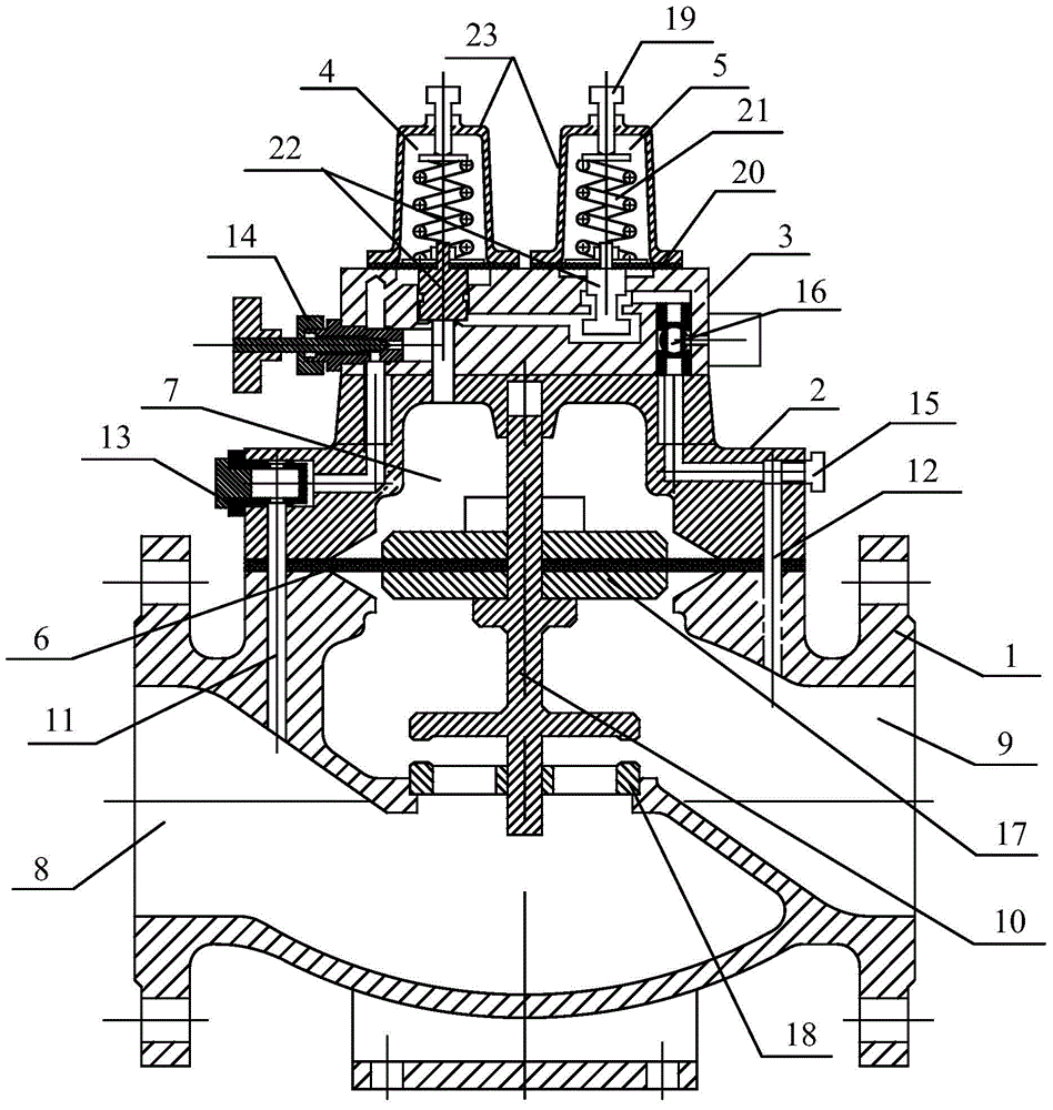
[0020] Such as figure 1 Shown: a control valve integrating decompression, pressure maintaining and isolation functions provided by the present invention, including main valve body 1, main valve cover 2, control valve cover 3, pressure maintaining control valve 4 and decompression control valve 5. The main valve cover 2 is set on the main valve body 1, the control valve cover 3 is set on the main valve cover 2, the pressure maintaining control valve 4 and the pressure reducing control valve 5 are both set on the control valve cover 3, the pressure maintaining control valve 4 and pressure reducing control valve 5 are all made up of adjusting screw rod 19, diaphragm 20, spring 21, control valve core 22 and control valve body 23. The main valve body 1 is provided with a main control valve diaphragm 6, a main control ...


PUM


Abstract

The invention discloses a control valve integrated with functions of pressure reducing, pressure maintaining and separating and the application thereof. The control valve comprises a main valve body, a main valve cover, a control valve cover, a pressure maintaining control valve and a pressure reducing control valve, wherein the main valve cover is arranged on the main valve body, a main control valve diaphragm is arranged between the main valve cover and the main valve body, and a main valve control cavity is formed between the main control valve diaphragm and the main valve cover; the control valve cover is arranged on the main valve cover, the pressure maintaining control valve and the pressure reducing control valve are both arranged on the control valve cover, the main valve body is provided with a water inlet, a water outlet and a main control valve core which is used for controlling the switching on and off of the water inlet and the water outlet, a pressure maintaining passage which leads to the pressure maintaining control valve is arranged in a position, which is close to the water inlet, of the main valve body, the pressure maintaining passage is communicated with the main valve control cavity, and a pressure reducing passage which leads to the pressure reducing control valve is arranged in a position, which is close to the water outlet, of the main valve body. The control valve disclosed by the invention is integrated with the functions of pressure reducing, pressure maintaining and separating and can be applied to a direct-connection heating device.

Description

technical field [0001] The invention relates to a control valve, in particular to a control valve which integrates the functions of decompression, pressure maintaining and isolation and its application. Background technique [0002] At present, pressure reducing valves and isolation valves are installed in the pipelines of the middle and low areas of district heating in high-rise buildings. Among them, the purpose of installing pressure reducing valves is to ensure that the return water in the high area cannot be overpressured, and it is also to ensure the safety and safety of the pipeline system. It is guaranteed that the heating of users in low areas cannot be affected. It can be seen from the structural principle of the pressure reducing valve that the pressure reducing valve can only control the maximum pressure of the return water in the high area to discharge to the main return water pipe network, but cannot guarantee that the return water pipe in the high area will no...

Claims


Application Information

Patent Timeline
Patent Type & Authority Applications(China)
IPC IPC(8): F16K1/00F16K31/36
CPCF16K1/00F16K17/34F16K31/36
Inventor 周洋
Owner 上海成峰流体设备有限公司
Why Eureka
Try Eureka