
Hydraulic brake unit and brake system of railway vehicle

A rail vehicle, hydraulic braking technology, applied in the direction of brake transmission, hydrostatic brake, hydrodynamic brake, etc., can solve the problems of brake shock, passenger injury, etc., to reduce the brake shock and improve the passenger experience. Effect

Active Publication Date: 2021-12-31
BYD CO LTD
View PDF7 Cites 0 Cited by
  • Summary
  • Abstract
  • Description
  • Claims
  • Application Information

AI Technical Summary

Problems solved by technology

[0003] In the above scheme, by controlling the second electromagnetic valve to be energized or de-energized, the active brake caliper is controlled to be connected or disconnected from the accumulator, if the first electromagnetic If the valve and the second solenoid valve are de-energized at the same time, the pressure in the accumulator will be applied to the brake cylinder instantly after passing through the pressure reducing valve, which will easily cause braking impact and cause injury to passengers

Method used


Image

  • Hydraulic brake unit and brake system of railway vehicle
  • Hydraulic brake unit and brake system of railway vehicle
  • Hydraulic brake unit and brake system of railway vehicle

Examples


Embodiment Construction

[0043] Embodiments of the present invention are described in detail below, examples of which are shown in the drawings, wherein the same or similar reference numerals designate the same or similar elements or elements having the same or similar functions throughout. The embodiments described below by referring to the figures are exemplary only for explaining the present invention and should not be construed as limiting the present invention.

[0044] The following disclosure provides many different embodiments or examples for implementing different structures of the present invention. To simplify the disclosure of the present invention, components and arrangements of specific examples are described below. Of course, they are only examples and are not intended to limit the invention. Furthermore, the present invention may repeat reference numerals and / or letters in different instances. This repetition is for the purpose of simplicity and clarity and does not in itself indicat...


PUM


Abstract

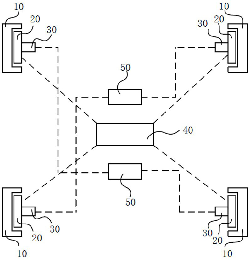
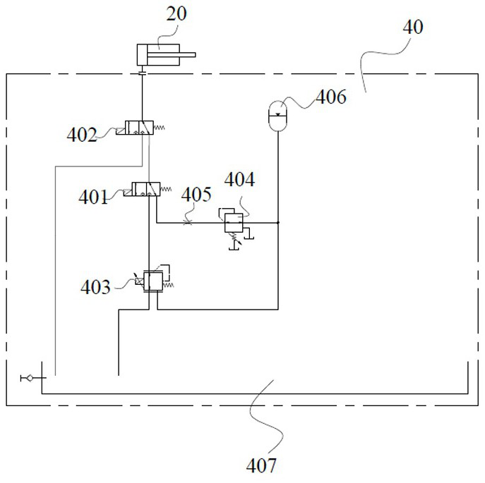
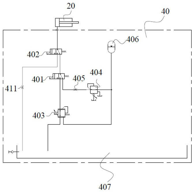
The invention provides a hydraulic brake unit of a railway vehicle, which is controlled by a hydraulic controller and comprises an energy accumulator, a proportional pressure reducing valve, a first electromagnetic directional valve, a second electromagnetic directional valve, a pressure reducing overflow valve and an oil tank; a brake caliper is connected with the second electromagnetic directional valve through an oil path, a first channel of the second electromagnetic directional valve is connected with the oil tank, a second channel of the second electromagnetic directional valve is connected with the first electromagnetic directional valve, a first channel of the first electromagnetic directional valve is connected with a proportional pressure reducing valve, a second channel of the first electromagnetic directional valve is sequentially connected with a pressure reducing overflow valve and an energy accumulator, and a first channel of the proportional pressure reducing valve is connected with an oil tank; and a second channel of the proportional pressure reducing valve is connected with the energy accumulator. The invention further provides a braking system of the railway vehicle.

Description

technical field [0001] The invention relates to the field of braking, in particular to a hydraulic braking unit of a rail vehicle and a braking system thereof. Background technique [0002] At present, in the field of rail vehicle braking, hydraulic braking is often used. Among them, the Chinese patent application number "CN201510408931.X", named "High-speed switching valve active tram hydraulic braking system" discloses the following technical solutions The hydraulic braking system of the present invention comprises a hydraulic unit, an active brake cylinder and an accumulator, the hydraulic unit comprises a fuel tank, an oil return system, an oil delivery system and a braking control system, and the braking control system is provided with a closed-loop control passage, Including 2 pcs 3 / 2-way valves. By controlling the energization or de-energization of the first high-speed switching valve, the connection or disconnection between the active brake cylinder and the fuel tan...

Claims


Application Information

Patent Timeline
Patent Type & Authority Applications(China)
IPC IPC(8): B60T13/68B60T13/74B61H11/06
CPCB60T13/686B60T13/74B61H11/06
Inventor 钟海斌宫昱滨张鑫谭志成
Owner BYD CO LTD
Learn More