Vapor-liquid separator input and output structure and manufacturing process thereof

A vapor-liquid separator, input and output technology, used in refrigerators, refrigeration components, refrigeration and liquefaction, etc., can solve the problems of cumbersome and easily damaged manufacturing processes, reduce manufacturing costs, reduce welding processes, and reduce quality hidden dangers Effect

Active Publication Date: 2014-08-13
新昌县杰创控股有限公司
View PDF6 Cites 1 Cited by
  • Summary
  • Abstract
  • Description
  • Claims
  • Application Information

AI Technical Summary

Problems solved by technology

[0004] The purpose of the present invention is to solve the problem that the welding spot between the steel pipe and the upper end cover in the existing gas-liquid separator steel pipe type input and output structure is easily damaged during the welding manufacturing process and the manufacturing process is cumbersome, and to provide an input and output structure with The input and output structure and manufacturing process of the gas-liquid separator with good welding firmness of the upper end cover of the gas-liquid separator and simple manufacturing process

Method used


Image

  • Vapor-liquid separator input and output structure and manufacturing process thereof
  • Vapor-liquid separator input and output structure and manufacturing process thereof

Examples


Embodiment Construction

[0014] Specific embodiments of the present invention will be described in detail below in conjunction with the accompanying drawings.

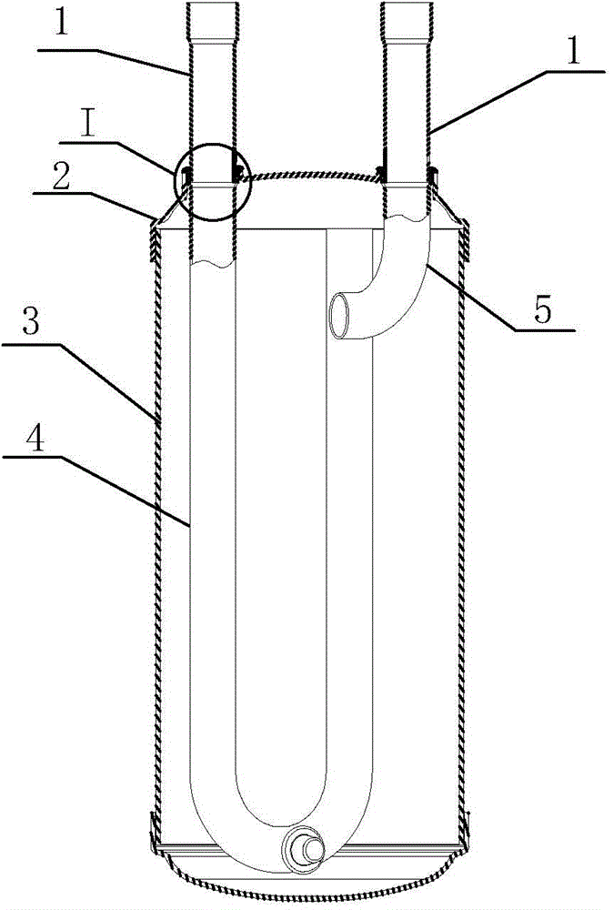
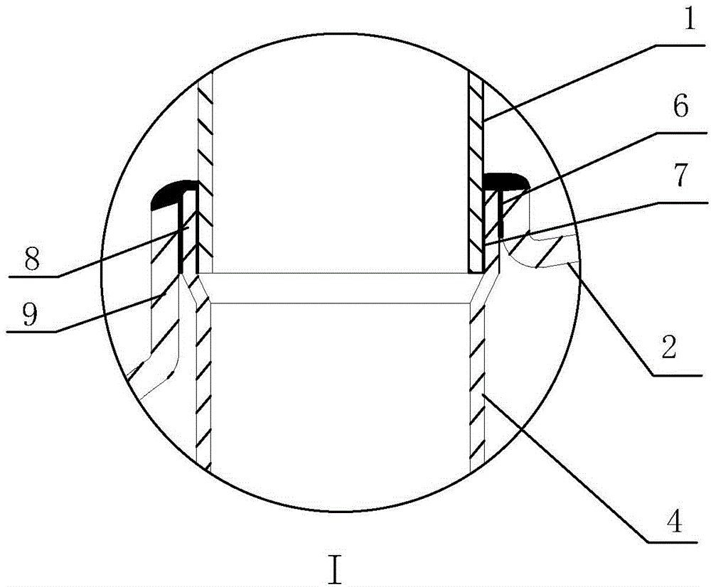
[0015] Such as figure 1 and figure 2 As shown, the input and output structure of the gas-liquid separator of the present invention includes a tank body 3, an upper end cover 2, a stainless steel input pipe 5 and a stainless steel output pipe 4, the upper end cover 2 is sealed at the end of the tank body 3, and the upper end cover 2 is provided with Inlet and outlet, the inlet and outlet on the upper end cover 2 are provided with a flanging part 9, the flanging part 9 is an outer flanging, the stainless steel input pipe 5 and the stainless steel output pipe 4 pass through the inlet and the outlet respectively, and the stainless steel The outer ends of the input pipe 5 and the stainless steel output pipe 4 are provided with flared portions 8, and each flared portion 8 is inserted with a copper connecting pipe 1, and the bottom end surface of t...


PUM


Abstract

The invention provides a vapor-liquid separator input and output structure and a manufacturing process thereof, which belong to the technical field of refrigerating system part manufacturing. The vapor-liquid separator input and output structure comprises a tank, an upper end cover, a stainless steel input pipe and a stainless steel output pipe, wherein the upper end cover covers the end part of the tank and is provided with an inlet, an outlet and flanging parts at the inlet and the outlet, the stainless steel input pipe penetrates through the inlet, the stainless steel output pipe penetrates through the outlet, the outer end of the stainless steel input pipe and the outer end of the stainless steel output pipe are respectively provided with a flaring part, a copper insertion pipe is inserted into each flaring part, and the bottom end of each copper insertion pipe, each flaring part and each flanging part are fixed in a welding manner for forming a five-layer structure consisting of a copper insertion pipe, a first flux layer, a flaring part, a second flux layer and an upper end cover flanging part from inside to outside. The manufacturing process of the vapor-liquid separator input and output structure comprises the following steps: step one, manufacturing the flanging parts; step two, manufacturing the flaring parts of the input and output pipes; step three, preparing the copper insertion pipes; step four, respectively welding the input pipe and the output pipe. The welding working procedures are reduced, the manufacturing cost is lowered, the welding firmness is improved, and the potential quality hazards are reduced.

Description

technical field [0001] The invention belongs to the technical field of refrigeration system component manufacturing, and in particular relates to an input and output structure of a gas-liquid separator and a manufacturing process thereof. Background technique [0002] As we all know, the gas-liquid separator is a commonly used gas-liquid separation and oil return device in the refrigeration system. In order to prevent the liquid refrigerant from directly entering the pump body of the compressor in the refrigeration system and causing damage to the pump body, it is usually installed between the compressor and the evaporator. A vapor-liquid separator is installed vertically to separate the gas refrigerant from the liquid refrigerant to improve the operation quality and efficiency of the refrigeration system. The vapor-liquid separator currently on the market generally includes a tank body, an upper end cover, a lower end cover, an input pipe, The output pipe and filter, the ...

Claims


Application Information

Patent Timeline
Patent Type & Authority Applications(China)
IPC IPC(8): F25B43/00B23P15/00
Inventor 吴琼张水华丁贤斌傅李钢
Owner 新昌县杰创控股有限公司
Why Eureka
Try Eureka