Particle filter-based improved RAIM (Receiver Autonomous Integrity Monitoring) anti-deception jamming method

A deceptive jamming and particle filtering technology, applied in radio wave measurement systems, satellite radio beacon positioning systems, measurement devices, etc., can solve the problem of ignoring residual vector correlation and similarity, to protect interests and ensure positioning accuracy Effect

Active Publication Date: 2014-08-13
HARBIN INST OF TECH
View PDF4 Cites 14 Cited by
  • Summary
  • Abstract
  • Description
  • Claims
  • Application Information

AI Technical Summary

Problems solved by technology

The traditional RAIM is only aimed at the measurement failure of a single satellite at first. Although some people have corrected the RAIM technology for the measurement failure of multiple satellites, it ignores the correlation and similarity between the residual vectors, which makes the interference source possible. take the opportunity

Method used


Image

  • Particle filter-based improved RAIM (Receiver Autonomous Integrity Monitoring) anti-deception jamming method
  • Particle filter-based improved RAIM (Receiver Autonomous Integrity Monitoring) anti-deception jamming method
  • Particle filter-based improved RAIM (Receiver Autonomous Integrity Monitoring) anti-deception jamming method

Examples


specific Embodiment approach 1

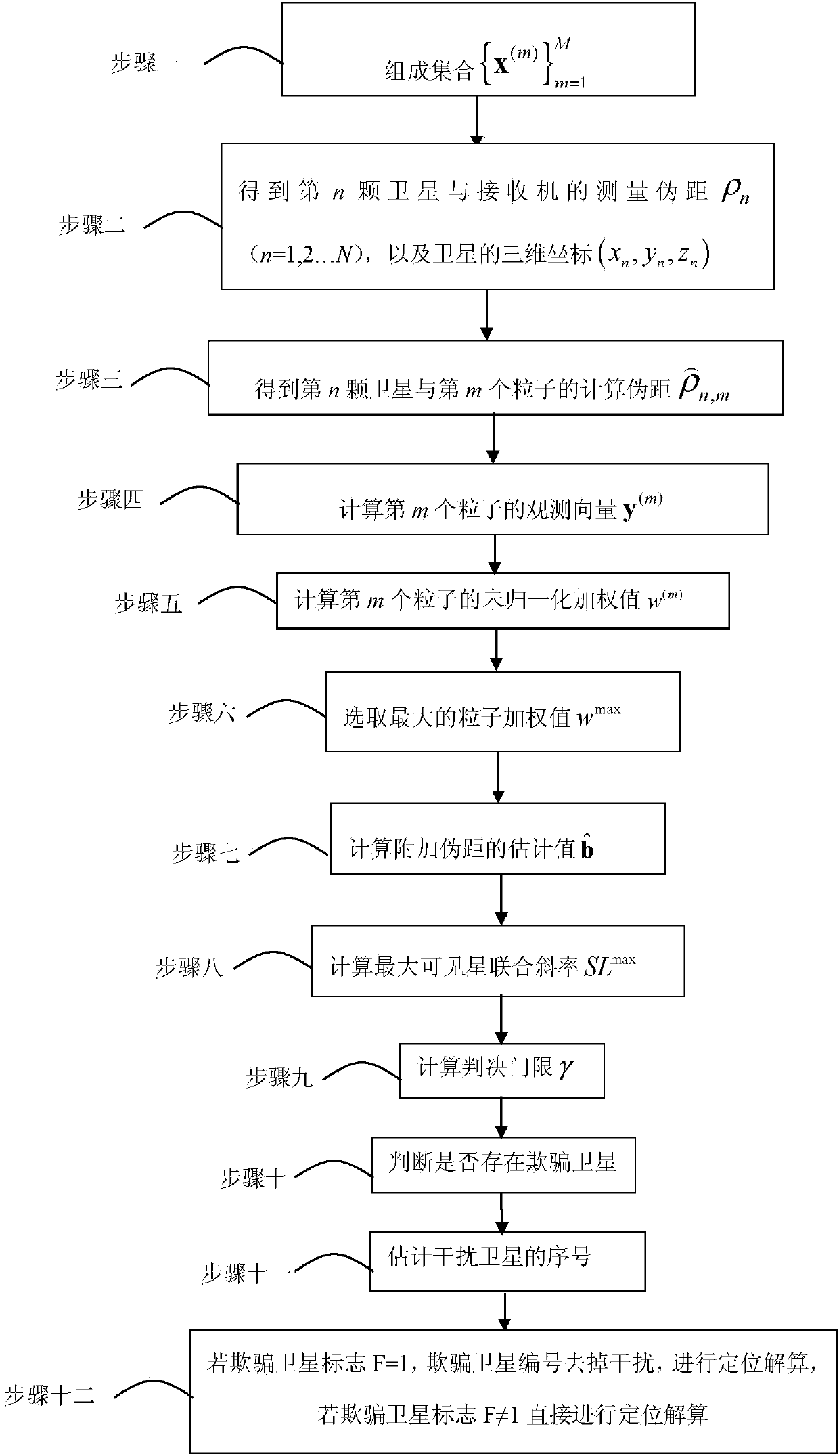
[0039] Specific Embodiment 1: An improved RAIM anti-spoofing interference method based on particle filter in this embodiment is specifically prepared according to the following steps:

[0040] Step 1. The estimated value of the receiver state is Indicates the estimated value of the receiver's three-dimensional coordinates, represents the estimated value of the receiver clock bias, in M particles are obtained in the neighborhood of , forming a set where x (m) =(x U,m ,y U,m ,z U,m ,δt U,m ) represents the mth receiver state particle, (x U,m ,y U,m ,z U,m ) represents the three-dimensional coordinates of the receiver, δt U,m Indicates receiver clock bias, m=1, 2....M;

[0041] Step 2. Set the number of currently visible satellites as N, measure the pseudo-range between each satellite and the receiver, and obtain the measured pseudo-range ρ between the nth satellite and the receiver n (n=1,2...N), and the three-dimensional coordinates of the satellite (x n ,y n ...

specific Embodiment approach 2

[0067] Specific embodiment two: the difference between this embodiment and specific embodiment one is: the maximum observation vector y obtained according to step six in step seven max , to compute an estimate of the additional pseudorange for:

[0068] b ^ = ( S T S ) - 1 S T y max ,

[0069] where S=(I-G(G T G) -1 G T ), is the residual vector matrix, G represents the satellite unit direction vector matrix, obtained by the following formula:

[0070] G = 1 1 1 1 ...

specific Embodiment approach 3

[0072] Specific embodiment three: the difference between this embodiment and specific embodiment one or two is: the estimated value of the additional pseudorange obtained according to step seven in step eight Calculate the maximum visible star joint slope SL max for:

[0073] SL max = max n 1 , n 2 , . . . , n Ns [ | | ( d max ) sub 1,2,3 | | | | ...


PUM


Abstract

The invention discloses a particle filter-based improved RAIM (Receiver Autonomous Integrity Monitoring) anti-deception jamming method. The invention relates to an improved RAIM anti-deception jamming method. For solving the problems of measurement failure of a single satellite, positioning misleading of a receiver by a control resolving flow, and neglecting of dependency and similarity among remaining vectors by RAIM, the invention provides a particle filter-based improved RAIM anti-deception jamming method. The particle filter-based improved RAIM anti-deception jamming method comprises the following steps: 1, forming a formula described in the specification; 2, obtaining a Rho n and three-dimensional coordinates of the satellite; 3, calculating a parameter described in the specification; 4, calculating y (m); 5, calculating w (m); 6, selecting wmax; 7, calculating a parameter described in the specification; 8, calculating a maximal visible satellite SLmax; 9, calculating a judgment threshold gamma; 10, judging the existence of a deception satellite; 11, estimating a sequence number of the deception satellite; and 12, if the mark F of the deception satellite is equal to 1, removing jamming, carrying out positioning resolving, and if F is not equal to 1, carrying out positioning resolving. The particle filter-based improved RAIM anti-deception jamming method is applied to the field of improved RAIM anti-deception jamming.

Description

technical field [0001] The invention relates to an improved RAIM anti-spoofing interference method based on particle filter. Background technique [0002] Positioning service is the most basic service provided by GNSS (Global Navigation Satellite System), and it is also the preferred target of spoofing jamming attacks. The jammer transmits or forges false signals with spoofed ephemeris information and pseudo-range information, and then transmits these signals to the corresponding frequency band in the receiver space. Usually, the jammer will use suppressive jamming to destroy the real GNSS signal link, and then increase the power of the jamming signal to increase its probability of being captured. The spoofed jamming signal captured by the receiver can destroy or even control the solution process, and then successfully mislead the receiver to locate. [0003] It has been observed that intentional spoofing jamming attacks are very similar to unintentional GNSS receiver pseu...

Claims


Application Information

Patent Timeline
Patent Type & Authority Applications(China)
IPC IPC(8): G01S19/21
CPCG01S19/21
Inventor 韩帅巩紫君孟维晓罗德巳
Owner HARBIN INST OF TECH
Why Eureka
Try Eureka