Rotor for rotary electric machine

A technology for rotating electrical machines and rotors, applied in the field of rotors of rotating electrical machines, can solve the problems of short-circuiting of the permanent magnet 112, the strength of the rotor core 111 decreasing, and the damage of the rotor 110, etc. Effect of suppressing magnetic flux short circuit

Active Publication Date: 2014-08-13
HONDA MOTOR CO LTD
View PDF10 Cites 16 Cited by
  • Summary
  • Abstract
  • Description
  • Claims
  • Application Information

AI Technical Summary

Problems solved by technology

[0010] However, in the rotor 110 of Patent Document 1, the protrusions 113a, 114a are formed integrally with the flux barriers 113, 114, respectively, so that the strength of the rotor core 111 decreases.
Therefore, when the rotor 110 is rotated at a high speed, the centrifugal force cannot be withstood, and the rotor 110 may be damaged.
[0011] Furthermore, when the radial widths of the flux barriers 113 and 114 are reduced in order to withstand the centrifugal force, the outer peripheral portions of the magnetic flux barriers 113 and 114 cannot be located near the outer peripheral surface of the rotor core 111, and the magnetic flux of the permanent magnets 112 short circuit becomes bigger

Method used


Image

  • Rotor for rotary electric machine
  • Rotor for rotary electric machine
  • Rotor for rotary electric machine

Examples


Embodiment Construction

[0114] Hereinafter, the rotor of the rotating electric machine according to each embodiment of the present invention will be described.

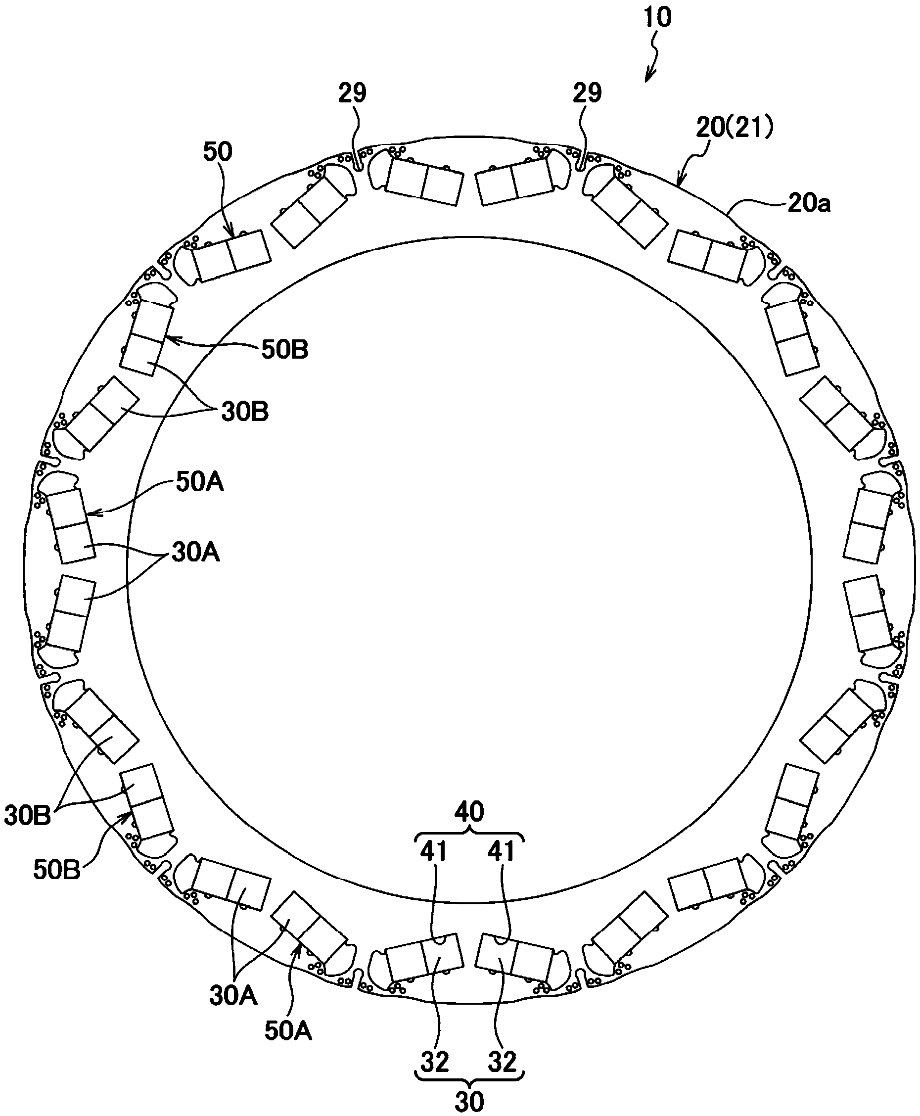
[0115] like figure 1 and figure 2 As shown, the rotor 10 of the rotating electrical machine according to the first embodiment includes a rotor core 20 and a plurality of magnetic pole portions 50, and is arranged on the inner peripheral side of a stator (not shown). On the outer peripheral side of a cylindrical rotor shaft (not shown), the plurality of magnetic pole portions 50 are formed at predetermined intervals in the circumferential direction inside the rotor core 20 .

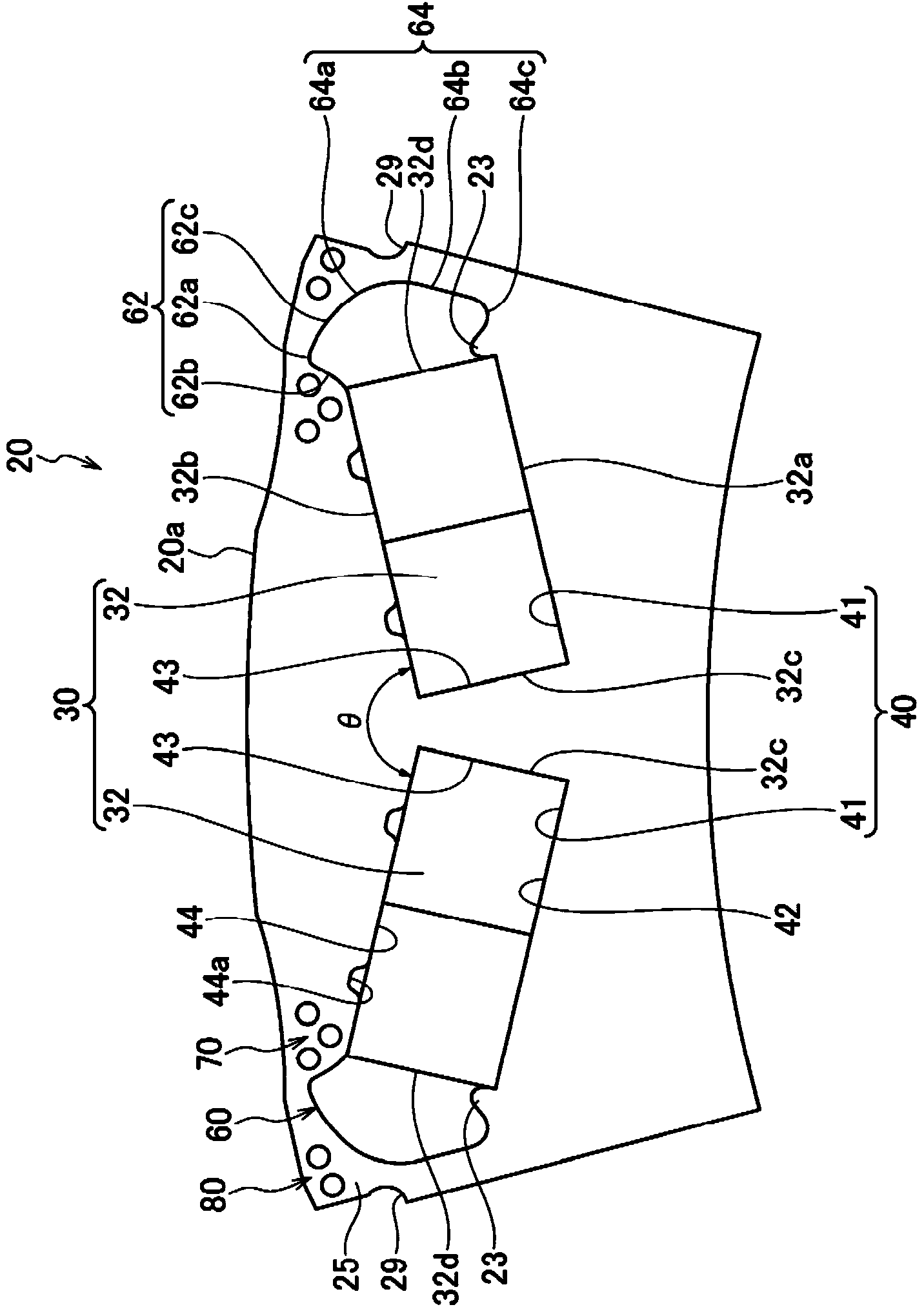
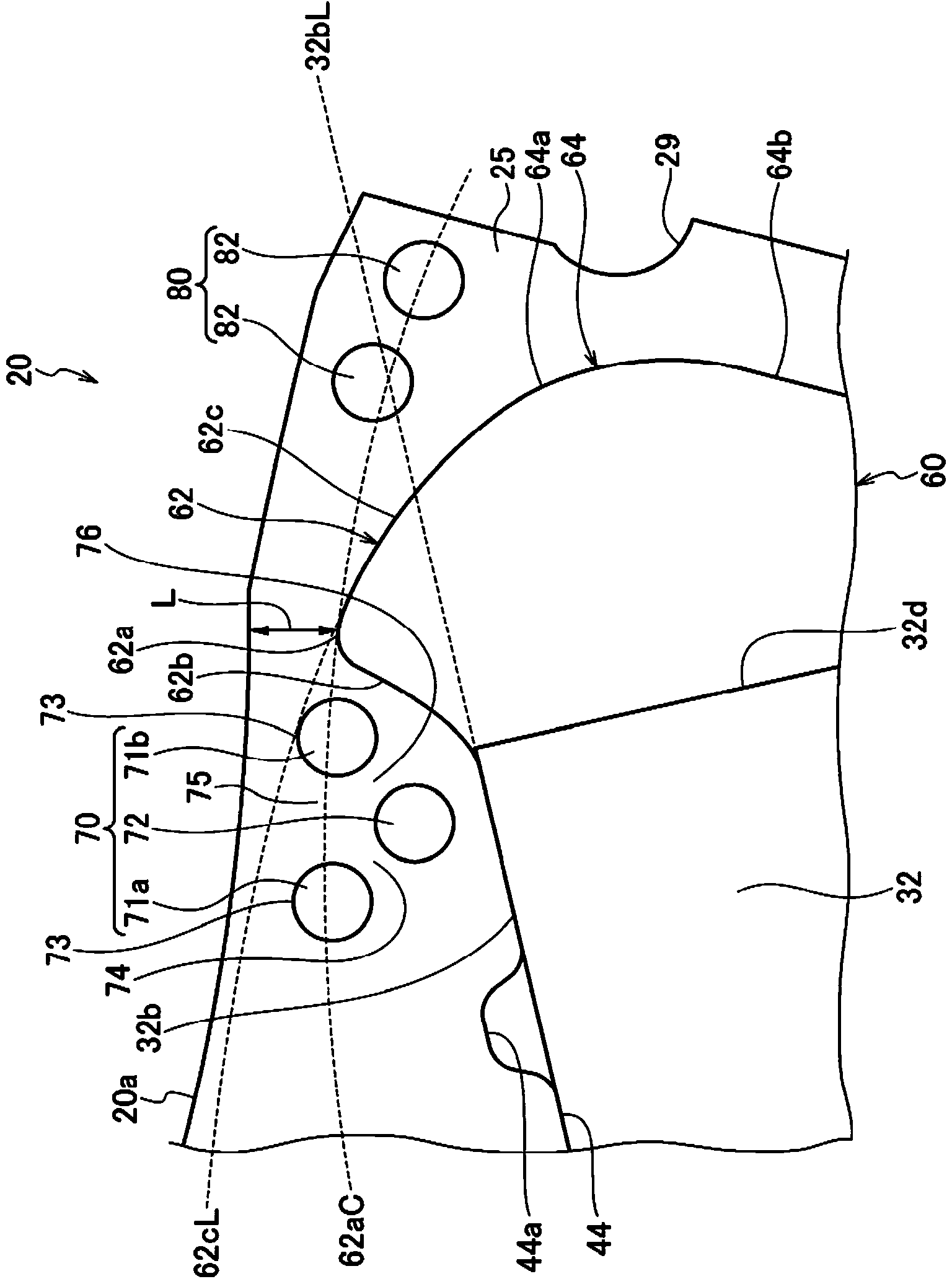
[0116] The rotor core 20 is formed by laminating a plurality of annular electromagnetic steel sheets of approximately the same shape, such as silicon steel sheets 21, and a plurality of magnet insertion holes 40 are formed at predetermined intervals along the circumferential direction. A groove 29 is recessed between 40 .

[0117] The magnetic pole portion 50 is co...


PUM


Abstract

The invention provides a rotor for a rotary electric machine to reduce occurrence of a magnetic flux short circuit of a permanent magnet and improve torque of the rotary rotor. A side barrier (60) is provided at a portion adjacent to a circumferential end face (32d) of the permanent magnet (32) and includes a projection barrier portion (62) projecting radially outwardly from an extension line (32bL) extending from an outer peripheral surface (32b) of the permanent magnet (32). A first air gap section (70) is provided at an area which is spaced apart from the projection barrier portion (62) and the magnet insertion hole (40) and faces a peripheral edge (62b) of a circumferentially central side of the projection barrier portion (62) with respect to the projection barrier portion and a circumferential end of the outer peripheral surface (32b) of the permanent magnet (32).

Description

technical field [0001] This invention relates to rotors for rotating electric machines. Background technique [0002] Conventionally, as a rotor used in a rotating electric machine, a structure in which a plurality of permanent magnets are arranged at predetermined intervals along the circumferential direction inside a rotor core is known (for example, refer to Patent Document 1). [0003] like Figure 16 As shown, in the rotor 110 of Patent Document 1, radial flux barriers (flux shields) 113 and 114 are provided on the outer peripheral portion of the rotor core 111 on the circumferential end face side of the permanent magnet 112 . In addition, protrusions 113 a , 114 a are provided on the outer peripheral end portions of the magnetic flux barriers 113 , 114 , and the distance 100L between the magnetic flux barriers 113 , 114 is shorter than the width 100W of the permanent magnet 112 . Also, a core portion 115 is provided between the protrusions 113 a , 114 a of the magneti...

Claims


Application Information

Patent Timeline
Patent Type & Authority Applications(China)
IPC IPC(8): H02K1/27
CPCH02K1/274H02K1/276H02K2213/03H02K1/2766
Inventor 相马慎吾白土英治壹岐友贵伊达靖典
Owner HONDA MOTOR CO LTD
Why Eureka
Try Eureka