Compressor

A compressor and compression mechanism technology, applied in the field of compressors, can solve problems such as overheating of the suction side of the cylinder, affecting the cooling capacity and power of the compressor, and difficulty in dissipating heat from the exhaust side, so as to reduce superheat and improve energy efficiency.

Inactive Publication Date: 2014-08-20
GUANGDONG MEIZHI PRECISION MFG
View PDF5 Cites 4 Cited by
  • Summary
  • Abstract
  • Description
  • Claims
  • Application Information

AI Technical Summary

Problems solved by technology

[0002] It is pointed out in related technologies that under actual operating conditions, the temperature of the oil pool in the compressor is relatively high, and the cylinder inside the compressor is immersed in the oil pool as a whole. Due to heat transfer, the suction side of the cylinder is overheated, while the exhaust side The heat is difficult to dissipate, which seriously affects the cooling capacity and power of the compressor

Method used


Image

  • Compressor
  • Compressor
  • Compressor

Examples


Embodiment 1

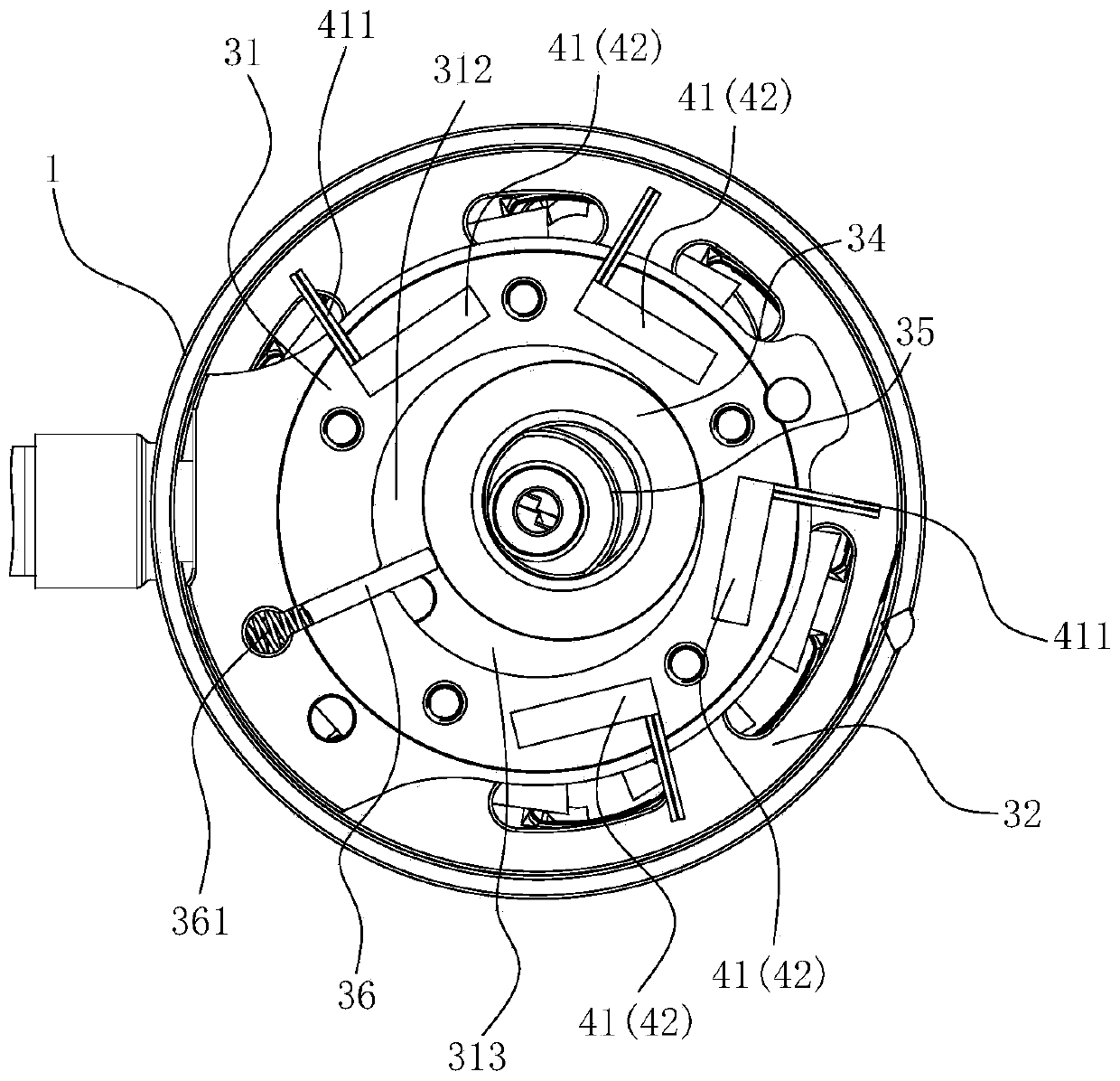
[0056] Such as figure 2 As shown, in this embodiment, the cylinder 31 is provided with four thermoelectric power generation components 41 or thermoelectric refrigeration components 42, two of which are located on the suction side of the cylinder 31 and arranged at intervals along the circumference of the cylinder 31, and the other two One is located on the exhaust side of the cylinder 31 and is also spaced apart from each other along the circumferential direction of the cylinder 31 .

[0057] Among them, these four can all be thermoelectric power generation components 41 , or all can be thermoelectric cooling components 42 , or one, two or three of them can be thermoelectric power generation components 41 , and the rest can be thermoelectric cooling components 42 .

Embodiment 2

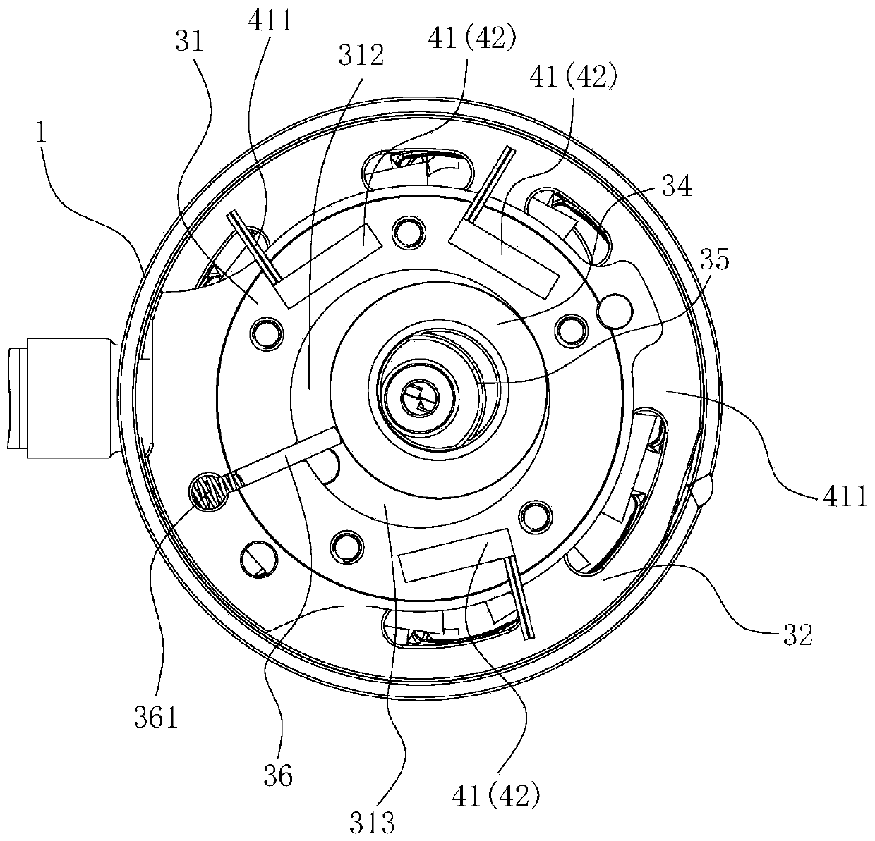
[0059] Such as image 3 As shown, the structure of this embodiment is substantially the same as that of Embodiment 1, wherein the same components use the same reference numerals, and the only difference lies in the number of thermoelectric power generation assemblies 41 or thermoelectric cooling assemblies 42 on the exhaust side of the cylinder 31 different.

[0060] refer to image 3 A total of three thermoelectric power generation assemblies 41 or thermoelectric refrigeration assemblies 42 are provided on the cylinder 31 , two of which are located on the suction side of the cylinder 31 and arranged at intervals along the circumference of the cylinder 31 , and the other is located on the exhaust side of the cylinder 31 .

[0061] Wherein, these three can all be thermoelectric power generation components 41 , or all can be thermoelectric cooling components 42 , or one or two of them can be thermoelectric power generation components 41 , and the rest can be thermoelectric cool...

Embodiment 3

[0063] Such as Figure 4 As shown, the structure of the present embodiment is substantially the same as that of the second embodiment, wherein the same components are marked with the same reference numerals, and the only difference is that no thermoelectric power generation assembly 41 or thermoelectric cooling assembly 42 is provided on the exhaust side of the cylinder 31 .

[0064] refer to Figure 4 , the cylinder 31 is provided with two thermoelectric power generation components 41 or thermoelectric refrigeration components 42 , both of which are located on the suction side of the cylinder 31 and are spaced apart from each other along the circumferential direction of the cylinder 31 .

[0065] Wherein, these two can both be the thermoelectric power generation component 41 , or both can be the thermoelectric cooling component 42 , or one of them can be the thermoelectric power generation component 41 and the other can be the thermoelectric cooling component 42 .


PUM


Abstract

The invention discloses a compressor, which comprises a shell, a motor, a compressing mechanism and a temperature difference device, wherein the motor is arranged in the shell; the compressing mechanism is connected with the motor and is provided with a cylinder; a sliding vane groove is formed in the cylinder; an air suction opening and an exhaust opening are formed in the compressing mechanism and are arranged in two sides of the sliding vane groove along the circumference of the cylinder; the temperature difference device is arranged on the cylinder and comprises at least one of a temperature difference generation component and a thermoelectric refrigerating component; the temperature difference generation component is arranged on at least one side of the sliding vane along the circumference of the cylinder; the thermoelectric refrigerating component is arranged on at least one side of the sliding vane along the circumference of the cylinder. According to the compressor, the overheat amount absorbed into gaseous cooling medium can be effectively reduced; the gas-liquid separation is realized; the heat in the compressing mechanism and the shell can be taken away by sufficiently evaporating liquid cooling medium; and through energy conversion, harmful heat source is converted to beneficial energy; the energy efficiency of the compressor is improved.

Description

technical field [0001] The invention relates to the field of refrigeration equipment, in particular to a compressor. Background technique [0002] It is pointed out in related technologies that under actual operating conditions, the temperature of the oil pool in the compressor is relatively high, and the cylinder inside the compressor is immersed in the oil pool as a whole. Due to heat transfer, the suction side of the cylinder is overheated, while the exhaust side The heat is difficult to dissipate, which seriously affects the cooling capacity and power of the compressor. Contents of the invention [0003] The present invention aims to solve at least one of the technical problems existing in the prior art. Therefore, an object of the present invention is to provide a compressor which has a simple structure and can effectively reduce the superheat of sucked gaseous refrigerant. [0004] According to the compressor of the present invention, it includes: a housing; a moto...

Claims


Application Information

Patent Timeline
Patent Type & Authority Applications(China)
IPC IPC(8): F04C29/04F04C29/00
Inventor 梅佩佩郭宏
Owner GUANGDONG MEIZHI PRECISION MFG
Why Eureka
Try Eureka