Laminating type piezoelectric brake adopting flexible amplifying structure and working method thereof

A technology of piezoelectric brakes and working methods, applied in the direction of drum brakes, brake types, brake actuators, etc., can solve the problems of extremely high brake assembly accuracy, the inability to obtain orders of magnitude amplification, stop concept and concept, etc., to achieve The effects of large thrust, simplified installation accuracy, and reduced assembly accuracy requirements

Inactive Publication Date: 2014-08-20
NANJING UNIV OF AERONAUTICS & ASTRONAUTICS
View PDF7 Cites 9 Cited by
  • Summary
  • Abstract
  • Description
  • Claims
  • Application Information

AI Technical Summary

Problems solved by technology

However, although piezoelectric ceramics can output a large thrust, the direct output displacement is very small (nanoscale), and it is difficult to be directly used to push the brake disc to achieve the braking effect.
However, the amplification effect of the ordinary mechanism is limited (up to several times), and the amplification of the order of magnitude cannot be obtained, and it is difficult to achieve a large displacement output.
In addition, the small displacement output requires extremely high brake assembly accuracy. Therefore, the previous piezoelectric brakes are only limited to ideas and concepts, and there is still a lack of feasibility for real applications.

Method used


Image

  • Laminating type piezoelectric brake adopting flexible amplifying structure and working method thereof
  • Laminating type piezoelectric brake adopting flexible amplifying structure and working method thereof
  • Laminating type piezoelectric brake adopting flexible amplifying structure and working method thereof

Examples


Embodiment Construction

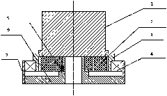
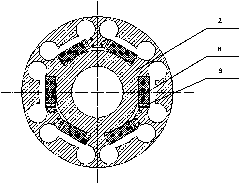
[0026] Please refer to figure 1 and figure 2 As shown, the present invention adopts the laminated piezoelectric brake with a flexible enlarged structure, including a brake rotating part 1, a ring 2, a brake disc 3, a bearing 4, a key 5, a brake support 6, a non-rotating part 7, a stack Piezoelectric ceramics 8 and wedges 9. Wherein the brake bracket 6 is installed in the non-rotating part 7, and the brake bracket 6 is stepped; the braking body is composed of a ring 2, and the ring 2 is located in the non-rotating part 7 and the inner circle of the ring 2 is in line with the brake support 6. The uppermost step is connected and positioned through the key 5, and the torque transmission is completed through the fixed fit of the key 5, and at the same time, the degree of freedom of rotation of the ring 2 along the axial direction is further restricted; the laminated piezoelectric ceramic 8 includes three pairs, and its embedded In the ring 2, a wedge 9 is provided on one side of...


PUM


Abstract

The invention discloses a laminating type piezoelectric brake adopting a flexible amplifying structure and a working method thereof. The piezoelectric brake comprises a non-rotation part, a brake support, a circular ring, a key, a brake disk and a rotating part, wherein the brake support, the circular ring, the key, the brake disk and the rotating part are installed in the non-rotation part. The circular ring is located in the non-rotation part, the inner circle of the circular ring and the brake support are connected through the key and located, and the inner circle of the brake disk and the outer circle of the circular ring are in clearance fit. The rotating part is installed on the circular ring and fixedly connected with the brake disk. The laminating type piezoelectric brake adopting the flexible amplifying structure further comprises laminating piezoelectric ceramic embedded in the circular ring, a wedge arranged on one side of the laminating piezoelectric ceramic and used for providing the pretightening force, and an isosceles triangle displacement amplifying structure used for amplifying and controlling extension displacement of the laminating piezoelectric ceramic. The laminating type piezoelectric brake adopting the flexible amplifying structure has the advantages of being small in size, easy to process, assemble and use, fast in response, easy to control and the like, and electromagnetic interference is avoided.

Description

Technical field: [0001] The invention relates to a laminated piezoelectric brake adopting a flexible amplifying structure and a working method thereof, belonging to piezoelectric actuators in the field of ultrasonic motors. Background technique: [0002] The friction clutch brake device is an indispensable executive mechanism in mechanical transmission, and it is required to output as large a braking torque as possible while consuming less energy and producing a small displacement. In the field of industrial brakes and automotive brakes, a large torque is usually required, and there is no specific requirement for accuracy and power consumption. Therefore, electromagnetic actuators are often used to drive the movement of the braking parts to achieve tightness and form a braking force (moment). . Due to the mechanism of electromagnetic actuation, it brings the disadvantages of relatively complex system, electromagnetic interference, and difficulty in miniaturization and contr...

Claims


Application Information

Patent Timeline
Patent Type & Authority Applications(China)
IPC IPC(8): F16D51/00F16D65/14F16D121/18F16D131/00
Inventor 陈超王寅陈海鹏赵淳生
Owner NANJING UNIV OF AERONAUTICS & ASTRONAUTICS
Why Eureka
Try Eureka