Light guide plate installing structure

A technology of installation structure and light guide plate, which is applied in the direction of optics, light guide, light source, etc., can solve the problems of inaccurate positioning of light guide plate, easy damage during installation, and short service life, so as to reduce the risk of light source being crushed and guarantee Normal use, not easy to deform

Inactive Publication Date: 2014-08-20
段清莲
View PDF8 Cites 2 Cited by
  • Summary
  • Abstract
  • Description
  • Claims
  • Application Information

AI Technical Summary

Problems solved by technology

[0006] The purpose of the present invention is to propose a light guide plate installation structure to solve the problems in the prior art that the light guide plate is not easy to install and easy to be damaged during the installation process due to the thinner light guide plate.
[0007] Another object of the present invention is to propose a light guide plate installation structure to solve the problem in the prior art that the light guide plate is not positioned accurately during the installation process, and is easily deformed due to thermal expansion, resulting in a short service life.

Method used


Image

  • Light guide plate installing structure
  • Light guide plate installing structure
  • Light guide plate installing structure

Examples


Embodiment Construction

[0027] The technical solutions of the present invention will be further described below in conjunction with the accompanying drawings and through specific implementation methods.

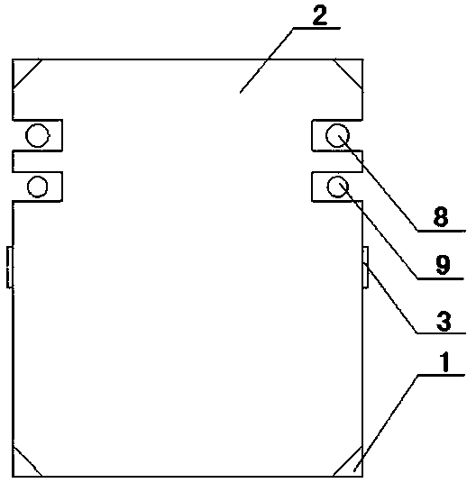
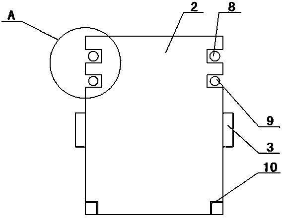
[0028] The invention proposes a light guide plate installation structure, which includes a light guide plate, a back plate and a plastic frame arranged in sequence. The light guide plate includes a first surface and a second surface oppositely arranged, and the second surface faces the back plate, such as figure 1 As shown, the four corners of the first surface of the light guide plate 2 are provided with downwardly recessed clamping positions 1 , and the side walls of the middle part of the light guide plate 2 are provided with outwardly protruding lugs 3 .

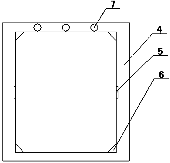
[0029] like figure 2 As shown, the four corners of the inner ring of the plastic frame 4 are provided with ribs 6 matching with the clamping positions 1 , and the middle part of the inner ring of the rubber frame 4 is provided with a positio...


PUM

PropertyMeasurementUnit
surface roughnessaaaaaaaaaa

Abstract

The invention relates to the technical field of light display structures and discloses a light guide plate installing structure. The light guide plate installing structure comprises a light guide plate, a back plate and a plastic frame, wherein the light guide plate, the back plate and the plastic frame are arranged in sequence. The light guide plate comprises a first face and a second face which are arranged oppositely. The second face faces the back plate. The four vertex angles of the first face of the light guide plate are provided with clamping positions recessed downwards. A protruding lug protruding outwards is arranged on the side wall of the middle of the light guide plate. Protruding ribs matched with the clamping positions are arranged on the four vertex angles of the inner ring of the plastic frame. A locating groove matched with the protruding lug is formed in the middle of the inner ring of the plastic frame. A groove is formed in the second face of the light guide plate. A rib plate matched with the groove is arranged on the back plate and used for locating the light guide plate and limiting expansion of the light guide plate in the installation process. According to the light guide plate installing structure, the thin light guide plate can be effectively prevented from being deformed, the light guide plate can be accurately located in the installation process, and the phenomenon that the light guide plate is prone to deformation due to the fact that the light guide plate is heated and expands is avoided.

Description

technical field [0001] The invention relates to the technical field of light display structures, in particular to a light guide plate installation structure. Background technique [0002] After years of development, liquid crystal display technology has gradually become a leader in display technology. The liquid crystal display screen produced with its technical support has become an indispensable and important component of display devices such as tablets and mobile phones. However, since the liquid crystal display panel itself does not emit light, it is necessary to arrange a backlight module under the liquid crystal display panel. [0003] Common distribution forms of light sources in liquid crystal display screens commonly used in the prior art are divided into bottom backlight and side backlight. For LCD screens that use side backlight to set the light source, the light guide plate is the most important optical component. The light source is set on the side of the light...

Claims


Application Information

Patent Timeline
Patent Type & Authority Applications(China)
IPC IPC(8): F21V17/10F21V17/16F21V8/00G02F1/13357F21Y101/02F21Y115/10
Inventor 于雯雯
Owner 段清莲
Why Eureka
Try Eureka