Heat pipe and manufacturing method thereof

A production method and heat pipe technology, which are applied in indirect heat exchangers, heat exchange equipment, lighting and heating equipment, etc., can solve the problems of insufficient heat dissipation performance of heat pipes, increase the effective evaporation area, increase the separation frequency, and increase the liquid return resistance. Effect

Inactive Publication Date: 2016-01-13
JIANGSU UNIV OF SCI & TECH
View PDF6 Cites 0 Cited by
  • Summary
  • Abstract
  • Description
  • Claims
  • Application Information

AI Technical Summary

Problems solved by technology

[0003] The purpose of the present invention is to overcome the defects of insufficient heat dissipation performance of existing heat pipes, provide a new high-efficiency heat pipe with good liquid-absorbing core material and high thermal conductivity working medium, and provide a manufacturing method of the high-efficiency heat pipe

Method used


Image

  • Heat pipe and manufacturing method thereof
  • Heat pipe and manufacturing method thereof

Examples


Embodiment Construction

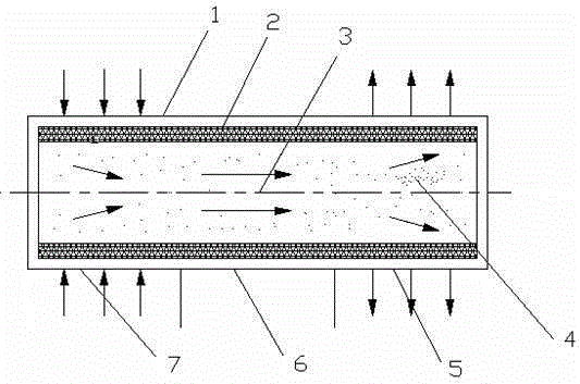
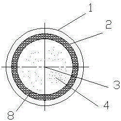
[0014] see figure 1 and figure 2 , the outermost part of the high-efficiency heat pipe of the present invention is the shell 1, and the innermost part is the steam chamber 3. Along the axial direction of the steam chamber 3, the steam chamber 3 is divided into an evaporating section 7, an adiabatic section 6 and a condensing section 5, the middle is an adiabatic section 6, and the two ends are respectively an evaporating section 7, a condensing section 5, an evaporating section 7 and a condensing section 5 The structure is the same. The shell 1 is cylindrical and made of red copper. The inner wall of the shell 1 is close to the capillary liquid-absorbing core layer 2. The capillary liquid-absorbing core layer 2 is composed of porous foam copper liquid-absorbing cores with different pore sizes. The wall thickness of the capillary liquid-absorbing core layer 2 is 0.2~1.0mm , the porosity is 50%~80%. The inner wall of the capillary liquid-absorbing core layer 2 is close to t...


PUM


Abstract

The invention discloses a heat pipe and a manufacturing method of the heat pipe. The heat pipe and the manufacturing method of the heat pipe can achieve cooling of electronic devices and a device. According to the heat pipe, a pipe shell is arranged on the outermost portion, a steam chamber is formed in the innermost portion, the steam chamber is divided into an evaporation segment, a thermal insulation segment and a condensation segment in the axial direction of the steam chamber, the thermal insulation segment is arranged in the middle, the evaporation segment and the condensation segment are arranged at the two ends respectively, a cylindrical capillary liquid absorption core layer formed by a multi-hole foamy copper liquid absorption core is closely attached to the inner wall of the pipe shell, holes in the multi-hole foamy copper liquid absorption core are different in hole diameter, a silk screen supporting frame is closely attached to the inner wall of the capillary liquid absorption core layer, the steam chamber is filled with a metal oxide water-based nanofluid working medium, the volume of the nanofluid working medium is 40% to 60% that of the evaporation segment, and metal oxide is aluminum oxide or copper oxide or silicon dioxide. According to the heat pipe and the manufacturing method of the heat pipe, nanofluid and multi-hole foamy copper are combined in the heat pipe, and the heat transfer efficiency of the heat pipe is improved.

Description

technical field [0001] The invention relates to the field of heat dissipation and cooling of electronic devices and devices, and specifically refers to a high-efficiency heat pipe, which realizes heat transfer by relying on the phase change of its internal working liquid, and realizes heat dissipation and cooling of electronic devices and devices. Background technique [0002] Due to the demand for miniaturization and integration of electronic equipment, the heat density generated by it is increasing, which will inevitably affect the reliability of electronic equipment. This requires that the heat dissipation equipment have higher thermal conductivity when taking heat dissipation measures. With the advantages of ultra-high thermal conductivity, heat transfer capacity and excellent isothermal properties, heat pipes have become the most effective heat dissipation device and have been widely used in air conditioning and refrigeration, electrical, nuclear power, waste heat recove...

Claims


Application Information

Patent Timeline
Patent Type & Authority Patents(China)
IPC IPC(8): F28D15/04F28F21/08
Inventor 姚寿广芦笙邓江伟盛冬刘健
Owner JIANGSU UNIV OF SCI & TECH
Why Eureka
Try Eureka