
Light field helmet display device increasing real stereoscopic impression

A helmet display, three-dimensional technology, applied in optics, optical components, instruments, etc., can solve the problem of not completely solving the problem of human eyes, system complexity, increased volume and weight It can achieve the effect of realizing realistic 3D display and solving the problems of convergence and convergence inconsistency.

Active Publication Date: 2014-08-20
BEIJING NEDPLUSAR DISPLAY TECH CO LTD
View PDF5 Cites 35 Cited by
  • Summary
  • Abstract
  • Description
  • Claims
  • Application Information

AI Technical Summary

Problems solved by technology

[0003] In the field of three-dimensional display, the image to be displayed provided has stereoscopic information, that is to say, the provided image has a certain depth, and the virtual object to be displayed is imaged in the front and back of the focal plane. The traditional head-mounted display can only give human eyes Provide the display information of a single focal plane. In order to see the object clearly, the human eye needs to adjust the lens of the human eye to make the human eye focus on this focal plane. The greater the difference between the depth of the virtual object and the depth of the focal plane, the difference between the convergence and convergence of the human eye It will be bigger, which will cause discomfort when people observe
[0005] Among them, the main method of the zoom surface helmet display is to quickly change the position of the imaging focal plane in the helmet display device during the use of the helmet display, so as to realize the rapid change of the position of the screen observed by the human eye along the depth direction. Specifically, it can be changed by changing The position of the image plane and the position of the optical system can be achieved by using liquid lenses, deformable mirrors, birefringent lenses or other electrically controllable ways to change the focal length of the optical system in the head-mounted display, but if the period of rapidly changing the position of the imaging plane is short Due to the persistence of vision of the human eye, there will be a problem of reconstructing multiple focal planes in front of the human eye
[0006] The solution of the multi-focal head-mounted display is to use multiple display devices in the head-mounted display, or to split one display device into multiple ones for use. In the process of designing the entire system, multiple display devices are stacked. In use, and multiple display devices form observation planes with different depths in space, increasing the number of display devices will alleviate the problem of convergence and inconsistency of the human eye, but the focal plane established in space is limited. It still does not reach the amount of spatial depth that the human eye can perceive, and does not fully conform to the attributes of real objects in the space observed by the human eye, and cannot completely solve the contradiction caused by the inconsistency of convergence and convergence of the human eye
[0007] Whether it is a head-mounted display with zoom plane or a multi-focal plane, it realizes three-dimensional display based on the principle of binocular parallax. A display device, or inserting a beam splitter or an electrically controllable zoom device will increase the complexity, volume and weight of the system, and will increase the discomfort perceived by the human body due to the increase in the complexity, volume and weight of the system, and even cause the system Too bulky to wear

Method used


Image

  • Light field helmet display device increasing real stereoscopic impression
  • Light field helmet display device increasing real stereoscopic impression
  • Light field helmet display device increasing real stereoscopic impression

Examples


Embodiment Construction

[0039] The present invention will be described in further detail below in conjunction with the accompanying drawings.

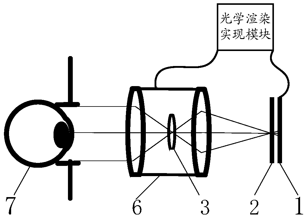
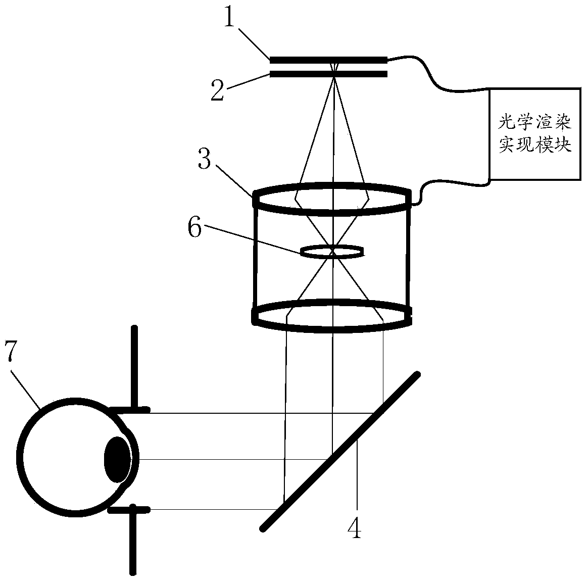
[0040] A real three-dimensional light field helmet display device, such as figure 1 As shown, it includes a microdisplay device 1, a microstructure array device 2, an optical eyepiece system 3, an optical adjustment device 6 and an optical rendering realization module. The microdisplay device 1, the microstructure array device 2 and the optical eyepiece system 3 are arranged in sequence, and the optical rendering The realization module is connected to the input end of the micro-display device 1, and the optical adjustment device 6 is connected to the optical eyepiece system 3 and the optical rendering realization module respectively;

[0041] The micro-display device 1 displays according to the gray value of each pixel received from the optical rendering implementation module;

[0042] The microstructure array device 2 refracts or filters the light waves emi...


PUM

PropertyMeasurementUnit
Exit pupil diameteraaaaaaaaaa

Abstract

The invention discloses a light field helmet display device increasing a real stereoscopic impression. The light field helmet display device comprises a micro display device, a micro structure array device, an optical eye lens system, an optical adjusting device and an optical rendering implementation module. Light emitted by different pixels of the micro display device is divided into beams through the micro structure array device, a dense space light field meeting the human eye natural vision is provided, the space light field is changed through the optical eye lens system, a visible area is controlled within the range capable of being observed through one eye, and therefore the problem that convergence and fusion of the human eyes are inconsistent in a helmet displayer is solved. The focal length of the optical eye lens system is changed at high speed through the optical adjusting device, the distribution of the space light field is changed fast, it means that more light fields are overlapped together, meanwhile, the pixels on the micro display system are synchronously refreshed through the optical rendering implementation module along with refreshing of the optical adjusting device, and therefore the resolution ratio of the light field helmet display device increasing the real stereoscopic impression is increased.

Description

technical field [0001] The invention relates to the field of virtual reality and augmented reality, in particular to a light field helmet display device for realizing real stereoscopic effect. Background technique [0002] The display device is an important part of the human-computer interaction interface in the field of virtual reality and augmented reality. On the one hand, the helmet-mounted display, as a near-eye display device, has become a research and development in the field of display in recent years due to its mobility, convenience and privacy. On the other hand, with the emergence of 3D movies, three-dimensional display has entered people's field of vision, and people have begun to apply head-mounted displays to the field of three-dimensional display. [0003] In the field of three-dimensional display, the image to be displayed provided has stereoscopic information, that is to say, the provided image has a certain depth, and the virtual object to be displayed is i...

Claims


Application Information

Patent Timeline
IPC IPC(8): G02B27/01G02B27/22
Inventor 王涌天宋维涛程德文刘越
Owner BEIJING NEDPLUSAR DISPLAY TECH CO LTD
Learn More