
End wall molded line modeling method for intermediate case of gas compressor

A compressor and intermediary technology, applied in image data processing, special data processing applications, instruments, etc., can solve problems such as unsatisfactory fitting effect of geometric line concave and convex curvature transition areas, limited scope of application, complicated implementation methods, etc. , to achieve the effect of good aerodynamic design index and strong versatility

Inactive Publication Date: 2014-08-20
NORTHWESTERN POLYTECHNICAL UNIV
View PDF2 Cites 10 Cited by
  • Summary
  • Abstract
  • Description
  • Claims
  • Application Information

AI Technical Summary

Problems solved by technology

[0003] Literature [1] (Que Xiaobin, Hou Anping, Zhou Sheng. Axisymmetric Equivalent Method for Transition Section of Axial Flow Compression System with Support Plate, Acta Aeronautica Sinica, 2010, Vol31, No.9.) Expressed as a quartic polynomial curve, the fitting effect on the concave and convex curvature transition areas of the geometric profile is not ideal (almost linear distribution), and the hub and casing profiles have as many as 10 free control variables respectively. Calculate and solve inconvenient
Literature [2] (Wallin F, Arroyo Osso, C., Johansson, T.G. Experimental and Numerical Investigation of an Aggressive Intermediate Turbine Duct: Part1—Flowfield at Design Inlet Conditions. AIAA paper AIAA-2008-7055, 2008.) try to The intermediary casing parameterization method of arc plus height distribution uses the combination of polynomial basis function and weight to regulate the geometric shape line, but the given basis function depends too much on the experience of the designer, and the implementation method is also relatively Complicated and limited in scope
Therefore, the current field of intermediary casing research lacks a simple (simple mathematical principle), high-efficiency (few free control variables), and strong versatility (the modeling method is suitable for most complex large-curvature geometric lines) end wall molding method

Method used


Image

  • End wall molded line modeling method for intermediate case of gas compressor
  • End wall molded line modeling method for intermediate case of gas compressor
  • End wall molded line modeling method for intermediate case of gas compressor

Examples


Embodiment Construction

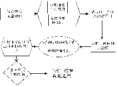
[0054] In the following, combined with the example of the intermediary casing of the compact compressor and the CFD calculation results, the detailed description is as follows: image 3 The specific implementation process of the present invention shown.

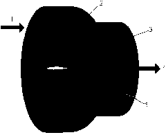
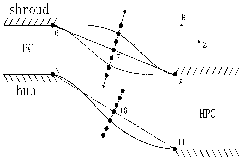
[0055] Step 1: Construct the end wall profile according to the geometric design parameters of the compressor intermediary casing, that is, to construct the 3D model of the compressor intermediary casing according to the known design parameters ( figure 1 ) for two-dimensional simplification ( figure 2 ), and perform dimensionless processing on the axial and radial coordinates of each point.

[0056] Among them, the geometric design parameters include: the Z-direction dimensionless coordinate Z of the entry point of the casing 6 , R to the dimensionless coordinate R 6 And the geometric angle of the casing inlet, the Z-direction dimensionless coordinate Z of the casing exit point 8 , R to the dimensionless coordinate R 8 ...


PUM


Abstract

The invention provides an end wall molded line modeling method for an intermediate case of a gas compressor. Fitting and adjusting of a hub and a molded line of the intermediate case of the gas compressor are completed through the Nom-Uniform Rational B-Spline curve and perpendicularity equal-division point moving method, the problem that a general method does not exist in the existing geometric design field of the intermediate case is solved, and complicated geometric molded lines such as the intermediate case with the large curvature change characteristic can be described mathematically and accurately. Meanwhile, the number of a plurality of free parameters needed in a traditional experience method is decreased to two, and therefore two-dimensional parameterized modeling is faster, simpler, more efficient and higher in generality, and good aerodynamic design indexes can be met.

Description

technical field [0001] The invention relates to a method for designing an intermediary casing of a compressor, in particular to a molding method for an end wall of an intermediary casing of a compressor. Background technique [0002] As the stator part connecting the high-pressure compressor and the low-pressure compressor of the turbofan engine, the intermediary casing of the compressor has a very important transitional role: on the one hand, it must rectify the airflow compressed by the upstream low-pressure compressor, and reduce its circumferential direction as much as possible. Inhomogeneity and circumferential and radial pressure gradients; on the other hand, two severe airflow deflections in the S-shaped flow channel must be completed to provide the best possible inlet conditions for the downstream high-pressure compressor stage. The current research on the intermediary casing of the compressor mainly focuses on the internal flow field analysis, aerodynamic performanc...

Claims


Application Information

Patent Timeline
IPC IPC(8): G06F17/50G06T17/00
Inventor 高丽敏邓小明冯旭栋刘波高磊
Owner NORTHWESTERN POLYTECHNICAL UNIV
Learn More