Rotor for rotating electric machine

A technology for rotating electrical machines and rotors, which is applied in the field of rotors for rotating electrical machines, and can solve the problems such as the decline in the anti-skid toughness of the rotating shaft 224, and achieve the effect of suppressing the press-in stress

Active Publication Date: 2014-08-20
HONDA MOTOR CO LTD
View PDF4 Cites 7 Cited by
  • Summary
  • Abstract
  • Description
  • Claims
  • Application Information

AI Technical Summary

Problems solved by technology

In this case, the shaft hole 222a also bulges toward the outer peripheral side, so the slip toughness with respect to the rotating shaft 224 decreases.

Method used


Image

  • Rotor for rotating electric machine
  • Rotor for rotating electric machine
  • Rotor for rotating electric machine

Examples


no. 1 approach

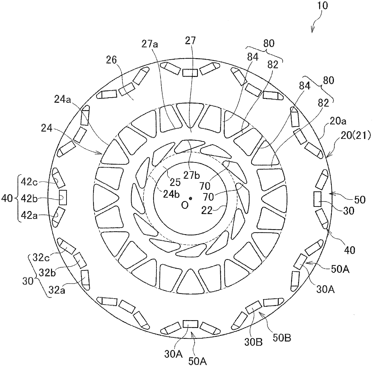
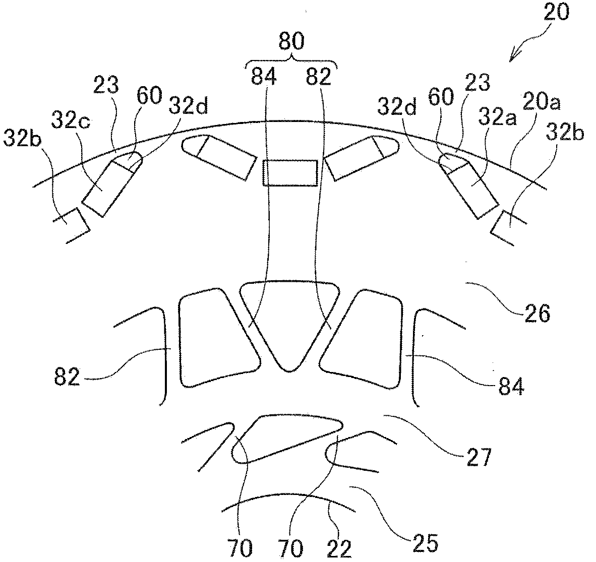
[0104] like figure 1 and figure 2 As shown, the rotor 10 of the rotating electrical machine according to the first embodiment includes a substantially annular rotor core 20 and a rotating shaft (not shown), and is disposed on the inner peripheral side of a stator (not shown). The rotor core 20 has A plurality of magnetic pole portions 50 formed at predetermined intervals along the circumferential direction are press-fitted into the shaft hole 22 formed in the center portion of the rotor core 20 with the rotating shaft. It should be noted, figure 1 , the symbol O is the center of the rotor 10 .

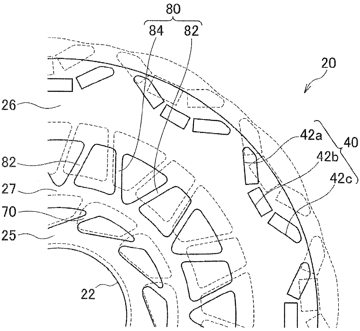
[0105] The rotor core 20 is formed by laminating a plurality of annular electromagnetic steel sheets having substantially the same shape, for example, silicon steel sheets 21 , and has a plurality of magnet insertion holes 40 formed at predetermined intervals along the circumferential direction.

[0106] The magnetic pole portion 50 is configured by inserting the permanent magnet...

no. 2 approach

[0132] Next, the rotor of the rotating electrical machine according to the second embodiment will be described. The rotor 10A of the rotating electrical machine of this embodiment is the same as the first embodiment in basic structure, and differs in the structure of the inner peripheral side rib 70 and the outer peripheral side rib 80 , so the same parts are omitted or simplified by attaching the same reference numerals. illustrate.

[0133] like Figure 7 and Figure 8 As shown, in the rotor 10A of the rotating electric machine according to this embodiment, the inner peripheral rib 70 includes: Figure 7 The first inner peripheral side rib 72 extending clockwise in the center; the other side in the circumferential direction ( Figure 7 The middle is the second inner peripheral side rib 74 extending counterclockwise.

[0134] The outer peripheral end portion of the first inner peripheral side rib 72 is connected to the outer peripheral side end portion of the second inner...

no. 3 approach

[0143] Next, the rotor of the rotating electric machine according to the third embodiment will be described. The rotor 10B of the rotating electrical machine of this embodiment is the same as the second embodiment in basic structure, and differs in the structure of the inner peripheral side rib 70 and the outer peripheral side rib 80 , so the same parts are omitted or simplified by attaching the same reference numerals. illustrate.

[0144] like Figure 10 and Figure 11 As shown, in this embodiment, as in the second embodiment, the included angle α formed by the first inner peripheral rib 72 and the second inner peripheral rib 74 is set to be larger than that between the first outer peripheral rib 82 and the second inner peripheral rib 82 . The angle β formed by the two peripheral side ribs 84 is large (α>β).


PUM


Abstract

A rotor includes a rotor core, a plurality of permanent magnets, and a rotating shaft. The rotor core includes a through-hole, an inner circumference-side rotor core, an outer circumference-side rotor core, an annular portion, a plurality of inner circumference-side ribs, and a plurality of outer circumference-side ribs. The through-hole is provided on a first inner circumference side of magnet insertion holes. The inner circumference-side rotor core is located on a second inner circumference side of the through-hole. The outer circumference-side rotor core is located on an outer circumference side of the through-hole. The annular portion has a substantially annular shape, and is being provided inside the through-hole. The plurality of inner circumference-side ribs connect the inner circumference-side rotor core and the annular portion and are provided at predetermined intervals in a circumferential direction.

Description

technical field [0001] This invention relates to rotors for rotating electric machines. Background technique [0002] Conventionally, as a rotor used in a rotating electrical machine, a rotor core in which a plurality of permanent magnets are arranged at predetermined intervals along the circumferential direction is known (for example, refer to Patent Documents 1 and 2). [0003] like Figure 13 As shown, the rotor 100 of Patent Document 1 is provided with a rotor core 101, and the rotor core 101 includes: an inner peripheral portion 103 surrounding a shaft press hole 102; a plurality of ribs 104 extending outward from the inner peripheral portion 103; 104 connected to the outer peripheral portion 105 . [0004] Here, the plurality of ribs 104 are inclined at a predetermined angle in the circumferential direction, and are formed in a so-called pinwheel shape. With such a configuration, the occurrence of deformation in the axial direction of the rib 104 is suppressed. [0...

Claims


Application Information

Patent Timeline
Patent Type & Authority Applications(China)
IPC IPC(8): H02K1/27
CPCH02K1/2706H02K1/2766H02K1/274H02K1/276H02K1/30
Inventor 山口直志井上雅志松冈庆久
Owner HONDA MOTOR CO LTD
Why Eureka
Try Eureka