System and method for filtering an optical signal to avoid fading and to optimize linearity

An optical signal and filter technology, which is applied in the field of improving the transmission quality of optical signals, and can solve the problems such as wavelength drift of optical signal carriers

Inactive Publication Date: 2014-08-20
TITAN PHOTONICS
View PDF0 Cites 0 Cited by
  • Summary
  • Abstract
  • Description
  • Claims
  • Application Information

AI Technical Summary

Problems solved by technology

In particular, changes in the ambient temperature of the optical signal generator will cause a shift in the carrier wavelength "λ" of the optical signal

Method used


Image

  • System and method for filtering an optical signal to avoid fading and to optimize linearity
  • System and method for filtering an optical signal to avoid fading and to optimize linearity
  • System and method for filtering an optical signal to avoid fading and to optimize linearity

Examples


Embodiment Construction

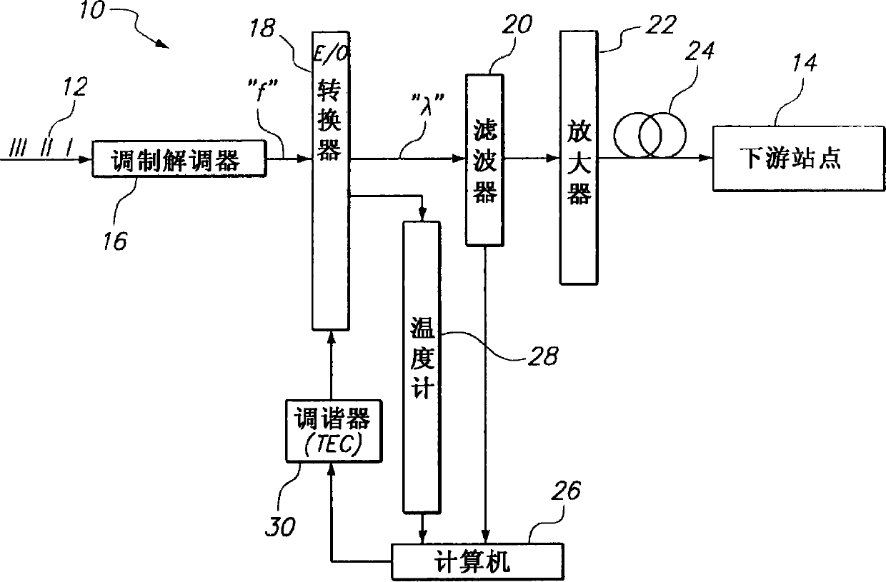
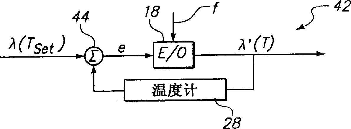
[0015] first reference figure 1 , shows a system according to the invention, generally indicated by reference numeral 10 . As shown, the system 10 is used to transmit a digital signal 12 to a downstream station 14 . To this end, the system 10 includes a modem 16 that first converts the digital signal 12 to a radio frequency (RF) signal "f". Subsequently, the electro-optic E / O converter 18 converts the RF signal "f" into an optical signal having a carrier wavelength "λ" whose upper sideband is "λ hi ”, the lower sideband is “λ low In both examples, the digital-to-RF conversion and RF-to-optical conversion can be accomplished using any method currently known in the art. Modem 16 and E / O converter 18 together serve as a Terminal of signal "λ".

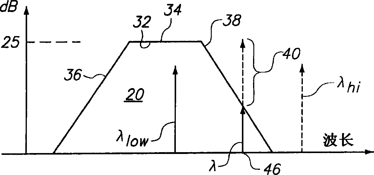
[0016] Once the optical signal "λ" is generated, the filter 20 is used for two different functional purposes. As one of them, filter 20 is used to remove one of the sidebands (“λ hi " or "λ low ”). On the other hand, filter 20 is u...


PUM


Abstract

A system for transmitting an optical signal over a fiber optic includes a terminal for generating the optical signal. Due to its modulation, the optical signal includes a carrier having a wavelength " ", with an upper sideband and a lower sideband. A tuner is connected with the terminal to adjust the wavelength " " of the carrier of the optical signal relative to a band pass filter. The purpose here is two-fold. For one, this adjustment eliminates a sideband of the optical signal, to avoid fading, and it suppresses the carrier of the optical signal, to enhance the OMI while maintaining the linearity of the signal.

Description

technical field [0001] The present invention generally relates to systems and methods for filtering optical signals. More particularly, the present invention relates to systems and methods for conditioning an optical signal relative to a bandpass filter to improve the transmission quality of the optical signal. The present invention is particularly, but not exclusively, for conditioning an optical signal relative to a bandpass filter to eliminate sidebands of the optical signal to avoid fading, while simultaneously suppressing the carrier to enhance the Optical Modulation Index (OMI) of the optical signal. Background technique [0002] When a light beam is used as the carrier of a signal and the light beam is transmitted through an optical fiber, several different phenomena associated with the transmission occur. First, when a beam of light and one or more other beams of light travel simultaneously on the fiber, interference can occur between the beam of light and one or mo...

Claims


Application Information

Patent Timeline
Patent Type & Authority Applications(China)
IPC IPC(8): H04B10/2507
CPCH04B10/2575H04B10/2507H04B10/07H04B10/5165
Inventor 孙震国
Owner TITAN PHOTONICS
Why Eureka
Try Eureka