
Carrier suppression device and method for electro-optical modulator

An electro-optical modulator and carrier suppression technology, applied in electromagnetic transmitters, electromagnetic wave transmission systems, electrical components, etc., can solve problems affecting carrier suppression or sideband suppression effects, and achieve the effect of improving signal-to-noise ratio.

Active Publication Date: 2022-01-11
BEIJING INST OF AEROSPACE CONTROL DEVICES
View PDF15 Cites 0 Cited by
  • Summary
  • Abstract
  • Description
  • Claims
  • Application Information

AI Technical Summary

Problems solved by technology

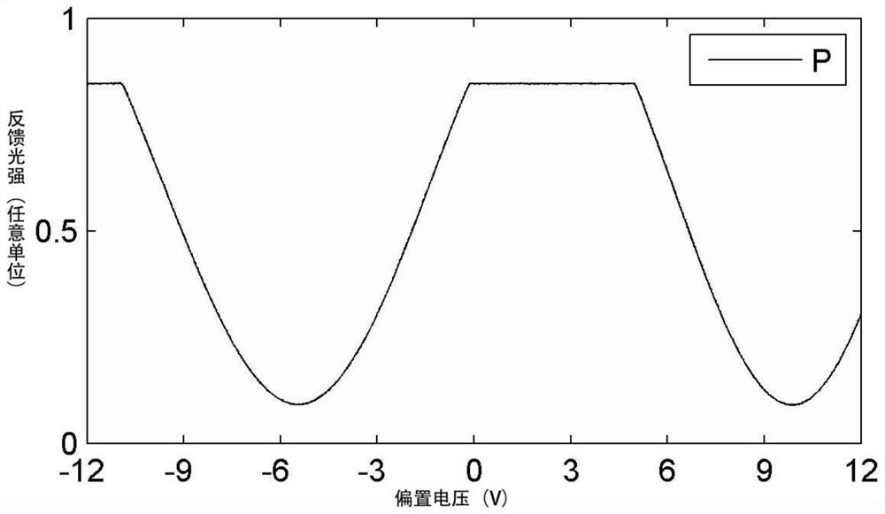
The premise of this method is that the optical insertion loss of the electro-optic intensity modulator is constant, but in fact, the insertion loss of the electro-optical intensity modulator changes with the change of temperature or carrier frequency, that is, the maximum output light of the electro-optical intensity modulator Or the minimum intensity changes, causing the adjusted bias voltage to be at a non-optimal operating point, which affects the carrier suppression or sideband suppression effect

Method used


Image

  • Carrier suppression device and method for electro-optical modulator
  • Carrier suppression device and method for electro-optical modulator
  • Carrier suppression device and method for electro-optical modulator

Examples


Embodiment Construction

[0029] Exemplary embodiments of the present disclosure will be described in more detail below with reference to the accompanying drawings. Although exemplary embodiments of the present disclosure are shown in the drawings, it should be understood that the present disclosure may be embodied in various forms and should not be limited by the embodiments set forth herein. Rather, these embodiments are provided for more thorough understanding of the present disclosure and to fully convey the scope of the present disclosure to those skilled in the art. It should be noted that, in the case of no conflict, the embodiments of the present invention and the features in the embodiments can be combined with each other. The present invention will be described in detail below with reference to the accompanying drawings and examples.

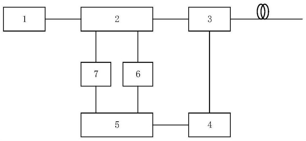
[0030] figure 1 It is a system structural block diagram of the electro-optical modulator carrier suppression device provided by the embodiment of the present...


PUM

PropertyMeasurementUnit
Line widthaaaaaaaaaa

Abstract

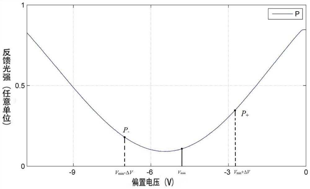
The invention discloses a carrier suppression device and method for an electro-optical modulator, and the system comprises an electro-optical modulator output light splitting detection and voltage feedback device; and stabilizing the control algorithm according to the bias voltage of the feedback light intensity. According to the invention, sampling feedback is carried out at the two ends of the bias working point, whether the bias working point drifts is judged, the direction and degree of drifting are judged, and the bias voltage is adjusted through feedback, so that effective suppression of carrier waves is realized, and the signal-to-noise ratio of sideband modulation signals is improved.

Description

technical field [0001] The invention belongs to the technical field of photoelectric automatic feedback control, and in particular relates to a carrier suppression device and method for an electro-optical modulator. Background technique [0002] Electro-optic intensity modulators are widely used in the fields of optical communication and fiber optic sensing. Taking the lithium niobate Mach-Zehnder electro-optical intensity modulator as an example, its interior consists of two waveguide arms and two Y-shaped branches. The input light is split into two equal beams at the first Y waveguide, and then interferes at the second Y branch through the two waveguide arms. By adjusting the high-frequency microwave signal loaded on the waveguide arm, the optical path difference between the two beams can be changed, so that the output light contains light components of different frequencies. [0003] Among them, the frequency of the microwave signal determines the frequency shift distan...

Claims


Application Information

Patent Timeline
IPC IPC(8): H04B10/516H04B10/54
CPCH04B10/54H04B10/5165
Inventor 潘亮杨潇君梅影杨勇李瑞艳马胜利
Owner BEIJING INST OF AEROSPACE CONTROL DEVICES
Learn More