Electromechanical parking braking mechanism and corresponding vehicle

A braking mechanism and mechanical technology, applied in the direction of manual starting device, etc., can solve the problems of difficult to detect faulty components, complex structure of characteristic components, difficult maintenance, etc., and achieve the effects of simple structure, high braking reliability and low cost

Active Publication Date: 2014-08-27
GREAT WALL MOTOR CO LTD
View PDF4 Cites 2 Cited by
  • Summary
  • Abstract
  • Description
  • Claims
  • Application Information

AI Technical Summary

Problems solved by technology

This patent has defects such as numerous components, complex layout, complex structure of characteristic components, high cost, difficult detection of faulty components, and difficult maintenance.

Method used


Image

  • Electromechanical parking braking mechanism and corresponding vehicle
  • Electromechanical parking braking mechanism and corresponding vehicle
  • Electromechanical parking braking mechanism and corresponding vehicle

Examples


Embodiment 1

[0037] Example 1 An electronically controlled mechanical parking brake mechanism

[0038] In the following description of this embodiment, front, back, left, right, up, and down are only set with reference to the accompanying drawings, and are not limited to absolute orientations.

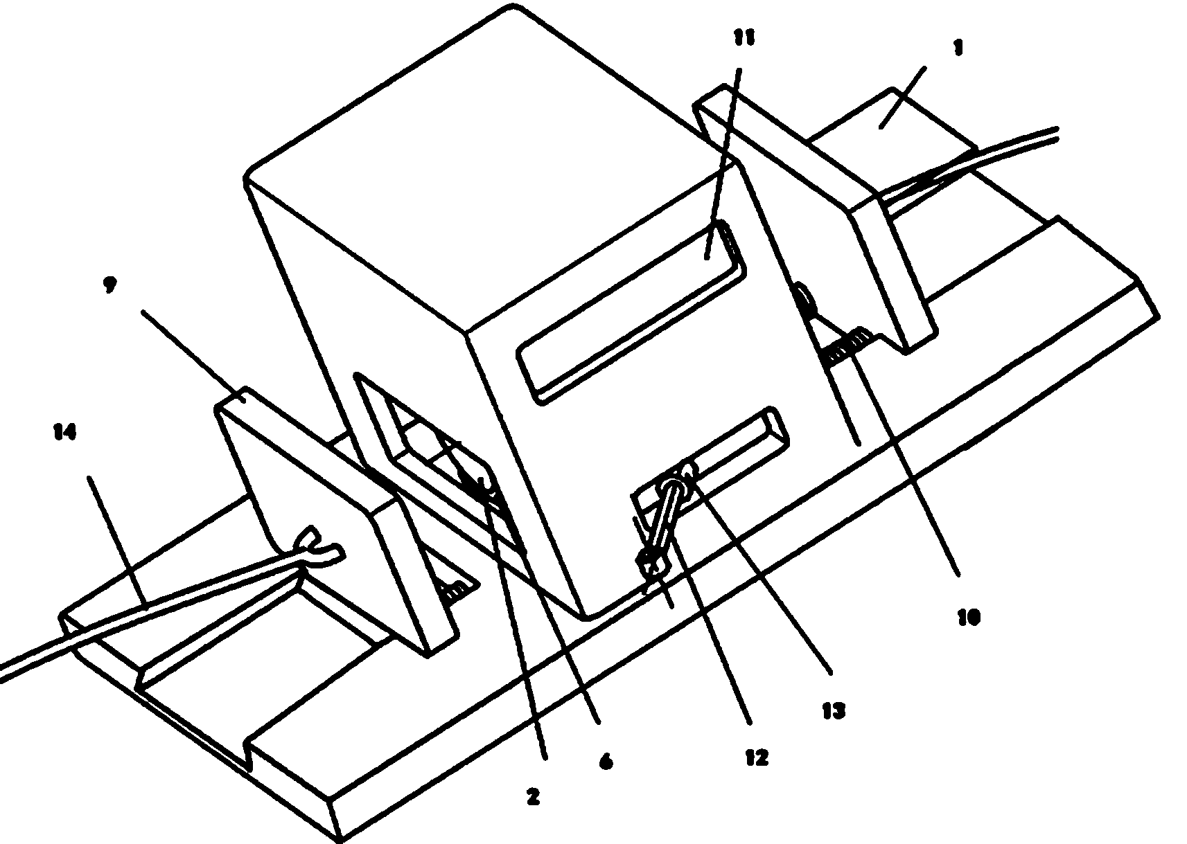
[0039] The electromechanical parking brake mechanism of this embodiment includes a base 1 .

[0040] refer to image 3 The base 1 is provided with a circular sunken groove 4, and two horizontally extending arc-shaped torsion springs 5 ​​are fixed on the surface of the groove 4, and the two torsion springs 5 ​​are arranged in a circular arrangement in the groove 4.

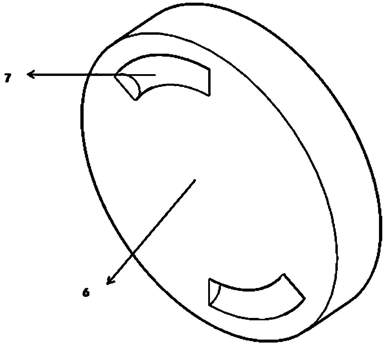
[0041] There is a disc 6 at the bottom that fits the groove 4 in the groove 4 . refer to Figure 4 , The disc 6 is provided with two up and down transparent arc-shaped grooves 7 compatible with the torsion spring 5, and the torsion spring 5 is limited in the arc-shaped groove 7. The arc center of torsion spring 5 corresponds up an...

Embodiment 2

[0057] Example 2 An electronically controlled mechanical parking brake mechanism

[0058] The electromechanical parking brake mechanism of this embodiment includes a base, referring to Embodiment 1:

[0059] The base is provided with a circular sunken groove, and the bottom of the groove is limited by a disc matching the groove.

[0060] A strip iron core extending left and right is fixed on the disk, and an electrified coil is wound on the outer wall of the iron core.

[0061] On the left and right sides of the base separated from the iron core, there are sunken dovetail guide grooves. The length of the dovetail guide groove extends along the left and right directions, and the width extends along the front and rear directions (the front refers to the direction perpendicular to the paper surface and away from the reader. ), the cross-section of the vertical plane along the width direction is dovetail-shaped.

[0062] There is a vertical block-shaped armature in the dovetai...

Embodiment 3

[0075] Example 3 a vehicle

[0076] A vehicle, which includes a parking brake device, differs from existing vehicles only in that its parking brake device is the electromechanical parking mechanism provided in Embodiment 1.

[0077] The structure of other parts of this embodiment is exactly the same as that of the prior art.


PUM


Abstract

The invention discloses an electromechanical parking braking mechanism and a corresponding vehicle. The mechanism comprises an iron core and an electrifiable coil and further comprises an armature. The armature is connected with an inhaul cable. The inhaul cable is drawn to control pressing and loosing of a brake piece. The armature is fixedly connected with a resetting spring, the winding direction and the electrification direction of the coil enable attraction force to be generated between the iron core and the armature, the control end of the electromagnetic coil is connected with an input / output (I / P) port of a programmable logic controller (PLC), and the PLC controls whether the coil is electrified. The corresponding vehicle is further provided. The mechanism applies attraction force to the armature by controlling electrification and power failure of the coil to further draw the inhaul cable and the brake piece to achieve wheel braking. The mechanism is simple in structure, compact in arrangement, smooth in force transfer process, high in reliability, low in cost, easy to maintain and good in maintenance. The braking mechanism is applicable to various vehicles.

Description

technical field [0001] The invention belongs to the field of braking of rotatable components, and relates to vehicle braking, in particular to an electronically controlled mechanical parking braking mechanism and a corresponding vehicle. Background technique [0002] The parking brake is mainly used to stabilize the vehicle after the vehicle has stopped, and to avoid accidents caused by rolling when the vehicle is parked on a slope. At present, the more commonly used are manual parking brake and electromechanical parking brake. in: [0003] ①The manual parking brake uses the brake lever to tighten the parking brake cable, causing the piston of the brake cylinder to tighten, compressing the brake block, and completing the parking brake. From the perspective of operation, it is more difficult to pull up the parking brake lever with the manual parking brake, especially for some female drivers, the handbrake is not in place, which will also bring safety hazards; [0004] ②El...

Claims


Application Information

Patent Timeline
Patent Type & Authority Applications(China)
IPC IPC(8): B60T7/08
Inventor 马志伟邢明星刘伟赵东华张杰
Owner GREAT WALL MOTOR CO LTD
Why Eureka
Try Eureka