Pavement crack detecting device and method based on depth and gray level images

A pavement crack detection device technology, applied in the interdisciplinary field of surveying and mapping science technology and instrument science, can solve the problem of uneven illumination and achieve the effects of comprehensive functions, convenient disassembly, and simple device integration

Active Publication Date: 2014-08-27
WUHAN WUDA ZOYON SCI & TECH
View PDF5 Cites 63 Cited by
  • Summary
  • Abstract
  • Description
  • Claims
  • Application Information

AI Technical Summary

Problems solved by technology

In view of this, the present invention focuses on the three-dimensional detection method of cracks, directly obtains the three-dimensional information of the road surface, and uses a high-power collimated laser to provide illumination for the section generated by the cracks in the road. The illu

Method used


Image

  • Pavement crack detecting device and method based on depth and gray level images
  • Pavement crack detecting device and method based on depth and gray level images
  • Pavement crack detecting device and method based on depth and gray level images

Examples


Embodiment Construction

[0034] The technical solutions of the present invention will be further described in detail below in conjunction with the accompanying drawings and specific embodiments, so that the advantages and characteristics of the present invention will become clearer along with the description.

[0035] Those skilled in the art can understand that although the following description involves many technical details related to the embodiments of the present invention, this is only an example for illustrating the principle of the present invention, and does not imply any limitation. The present invention can be applied to occasions other than the technical details exemplified below, as long as they do not deviate from the principle and spirit of the present invention.

[0036] In addition, in order to avoid making the description in this manual limited to redundant, in the description in this manual, some technical details that can be obtained in the existing technical documents may be omitt...


PUM


Abstract

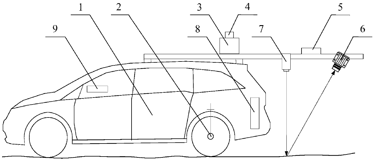
The invention discloses a pavement crack detecting device and method based on depth and gray level images. The pavement crack detecting device comprises a carrier platform (1), a camera shooting device (6), a line laser (7) and a calculating device (8), wherein the camera shooting device, the line laser and the calculating device are located on the carrier platform. The carrier platform (1) is used for moving in the pavement direction in the crack detecting process. The line laser (7) is used for emitting laser light perpendicular to a pavement while the carrier platform (1) moves. The camera shooting device (6) is used for continuously shooting laser lines, reflected by the pavement, of the linear laser light in a slant mode while the carrier platform (1) moves, imaging is conducted on a pavement fracture surface every time shooting is performed, and image data of the laser lines of a plurality of pavement fracture surfaces are generated. The calculating device (8) is used for generating depth data and gray level data of the corresponding pavement fracture surface according to the image data of the laser lines of each pavement fracture surface and splicing the depth data and the gray level data of each pavement fracture surface to form image data of a section of the pavement so as to conduct crack recognition.

Description

technical field [0001] This application belongs to the interdisciplinary field of surveying and mapping science and technology and instrument science, and involves image processing technology, mobile fine positioning technology and multi-sensor integration and synchronous control technology, especially relates to road surface crack detection methods and devices, which can be widely used in mobile road surveying and mapping, Road surface inspection, track inspection, tunnel inspection and other surveying and transportation fields. Background technique [0002] During the use of highways, affected by many factors such as the natural environment and driving loads, various damages are gradually formed on the surface of the highway. Cracks, as a common form of damage to the road surface, are extremely harmful to the highway. In order to save maintenance resources and ensure the safety and comfort of driving, it is necessary to accurately obtain parameter information such as the l...

Claims


Application Information

Patent Timeline
IPC IPC(8): E01C23/01
Inventor 李清泉毛庆洲熊智敏曹民张德津周瑾章丽萍
Owner WUHAN WUDA ZOYON SCI & TECH
Why Eureka
Try Eureka