Powerful and mechanical automatic-locking hydraulic cylinder

A powerful machine and hydraulic cylinder technology, applied in the field of hydraulic cylinders, can solve the problems that the accuracy and reliability cannot be guaranteed, the oil circuit hydraulic cylinder is easy to leak and repair, and the accuracy cannot meet the requirements. Simple and efficient inflatable, less difficult to process

Inactive Publication Date: 2014-08-27
CSIC ZHONGNAN EQUIP
View PDF10 Cites 22 Cited by
  • Summary
  • Abstract
  • Description
  • Claims
  • Application Information

AI Technical Summary

Problems solved by technology

When the hydraulic lock is kept at a certain position for a long time, due to problems such as pressure oil leakage, the accuracy often cannot meet the requirements. In the event of oil circuit failure, the accuracy and reliability cannot be guaranteed; hydraulic locks often require one-way Valves, reversing valves and other auxiliary components cooperate to realize the locking circuit. The use of these components makes the whole device take up a lot of space. At the same time, the increase of oil circuits brings problems of easy leakage and inconvenient maintenance to the hydraulic cylinder.

Method used


Image

  • Powerful and mechanical automatic-locking hydraulic cylinder
  • Powerful and mechanical automatic-locking hydraulic cylinder
  • Powerful and mechanical automatic-locking hydraulic cylinder

Examples


Embodiment Construction

[0028] The present invention will be described in detail below with reference to the accompanying drawings and examples.

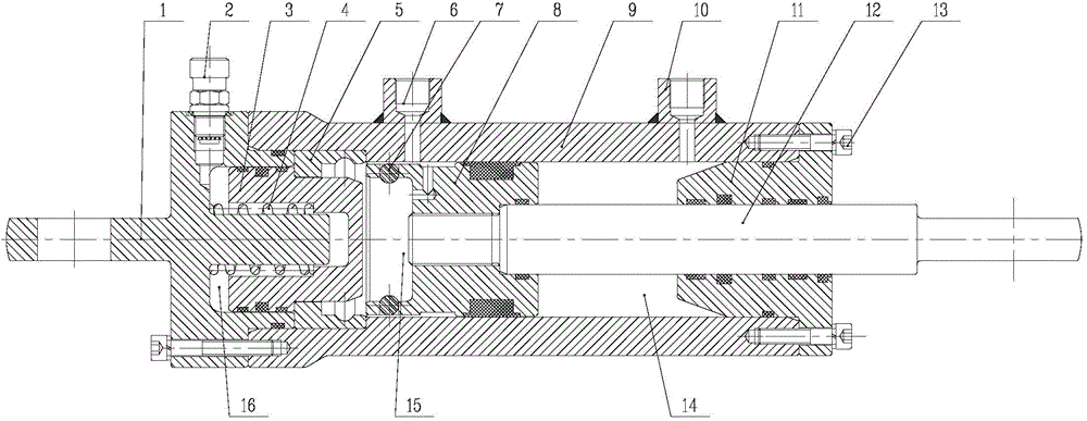
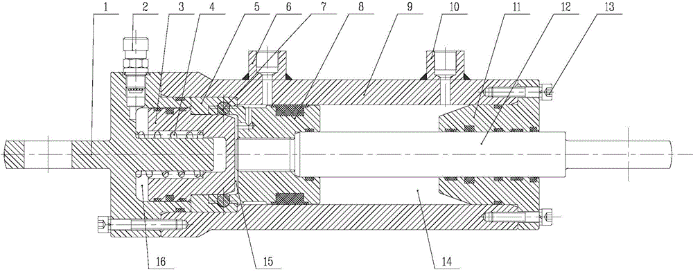
[0029] as attached figure 1 As shown, the present invention provides a powerful mechanical self-locking hydraulic cylinder, including a cylinder head 1, an air charging valve 2, a brake block 3, a spring 4, a locking block 5, a steel ball 7, a piston 8, a cylinder barrel 9, and a cylinder bottom 11 , piston rod 12 and screw 13;

[0030] Wherein, one end of the cylinder head 1 is provided with a coaxial annular groove and a guide column, and the outer peripheral surface of the cylinder head 1 is provided with an inflation valve 2 communicating with the annular groove;

[0031] The central hole on the brake block 3 is a step blind hole, the small diameter section of the step blind hole is in clearance fit with the guide column of the cylinder head 1, and the spring 4 is formed between the large diameter section of the step blind hole and the guide column of...


PUM


Abstract

The invention discloses a powerful and mechanical automatic-locking hydraulic cylinder, and belongs to the technical field of hydraulic cylinders. The two ends of a cylinder barrel are sealed by a cylinder cover and a cylinder bottom respectively. A guiding column of the cylinder cover is sleeved with a spring. The spring is sleeved with a brake block. The two ends of the spring abut against the cylinder cover and the brake block respectively. The outer circumferential face of the large diameter of the brake block is in sealing fit with the inner circumferential face of the cylinder cover. The end face of the end, with a large-diameter hole, of a locking block abuts against the end face of the step of an inner hole of the cylinder barrel, and the other end face of the locking block abuts against the end face, located at the portion of the cylinder barrel, of the cylinder cover. After a steel ball is put into a steel ball installation hole of a piston, the steel ball installation hole of the piston is matched with an inner hole of the cylinder barrel, and an annular groove of the piston corresponds to a rodless cavity oil port in the cylinder barrel. One end of a piston rod is fixed to a piston rod installation hole of the piston, and the other end of the piston rod penetrates through the cylinder bottom to be located outside the cylinder barrel. According to the powerful and mechanical automatic-locking hydraulic cylinder, the requirement for automatic locking after the piston rod is completely retracted can be met, and the locking state can be kept for a long time under the situation that pressure relief of a hydraulic system is completed or leakage happens until unlocking is actively achieved.

Description

technical field [0001] The invention relates to a hydraulic cylinder, in particular to a mechanical self-locking hydraulic cylinder, which belongs to the technical field of hydraulic cylinders. Background technique [0002] Self-locking hydraulic cylinders are currently widely used in military and aviation applications, as well as in engineering fields such as metallurgy and take-off and landing equipment. In many mechanical fields such as metallurgy and coal mines, hydraulic components need to lock the hydraulic cylinder in order to prevent the workpiece from shifting under the action of external force or self-weight (hydraulic cylinder standing upright) when the workpiece stops working. [0003] At present, hydraulic cylinders mainly rely on blocking pressure oil to lock hydraulic cylinders, which are prone to leakage, "negative pressure effect" and "soft leg phenomenon". Although there are many improved products, they have not fundamentally solved the problem. When the h...

Claims


Application Information

Patent Timeline
Patent Type & Authority Applications(China)
IPC IPC(8): F15B15/26F15B15/14
Inventor 杜浩斌郭明雷辉虎常征刘建魁许家勤
Owner CSIC ZHONGNAN EQUIP
Why Eureka
Try Eureka