Negative flow hydraulic control circuit, method, actuator and system

A control circuit and hydraulic system technology, applied in the direction of fluid pressure actuation system components, fluid pressure actuation devices, mechanical equipment, etc., can solve the problems of power consumption, large and medium power loss, and the inability to adjust the hydraulic system pressure, etc., to achieve Reduce the median power loss, reduce the median power loss, the effect of small pressure and displacement

Active Publication Date: 2016-02-17
中联重科土方机械有限公司
View PDF4 Cites 0 Cited by
  • Summary
  • Abstract
  • Description
  • Claims
  • Application Information

AI Technical Summary

Problems solved by technology

[0003] However, when the hydraulic system is not in action, in order to limit the displacement of the variable pump to the above-mentioned minimum state, the negative flow pressure signal cannot be too small, that is, the setting value of the relief valve cannot be too small. Therefore, when all valve stems are returned to the center position, even though the displacement of the variable pump has been reduced, there is still a large pressure in the hydraulic system (that is, negative flow pressure), which still consumes a lot of power
That is to say, in the prior art, when the hydraulic system is inactive, only the displacement of the variable pump can be controlled, but the pressure of the hydraulic system cannot be adjusted, and there is still a large median power loss

Method used


Image

  • Negative flow hydraulic control circuit, method, actuator and system
  • Negative flow hydraulic control circuit, method, actuator and system
  • Negative flow hydraulic control circuit, method, actuator and system

Examples


Embodiment approach

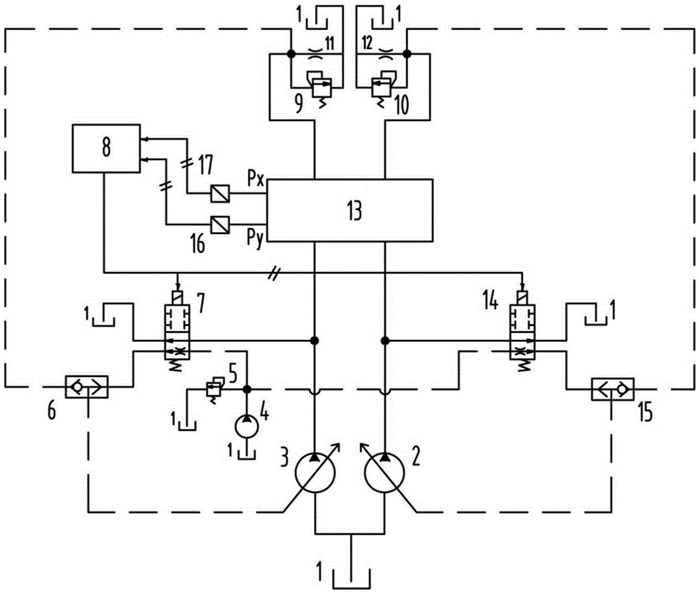
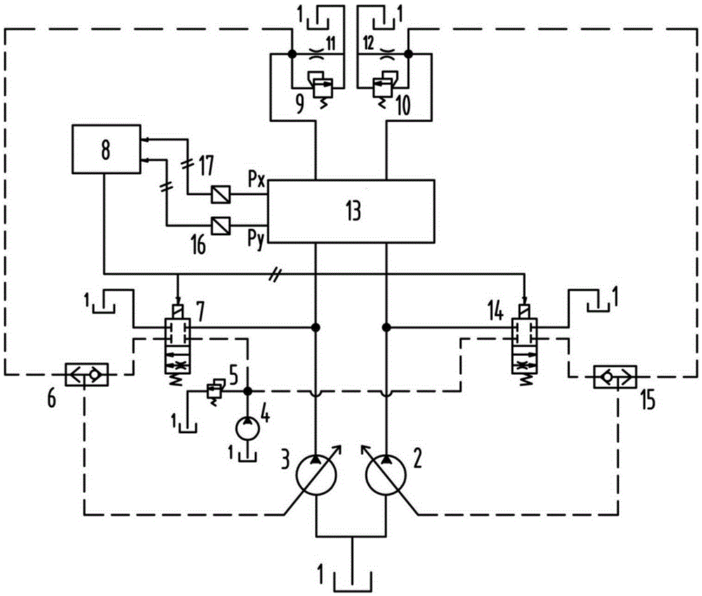
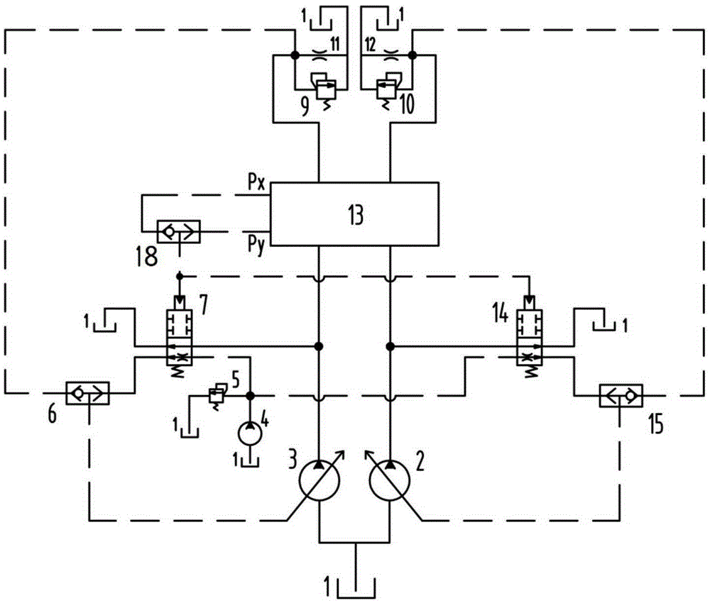
[0027] According to an embodiment of the present invention, the negative flow hydraulic control circuit may include an unloading valve, the first oil inlet of the unloading valve is connected to the corresponding oil outlet of the variable displacement pump, the first oil outlet is connected to the The hydraulic oil tank is connected to control the on-off of the unloading circuit.

[0028] Moreover, the negative flow hydraulic control circuit may also include a shuttle valve, wherein the first oil inlet of the shuttle valve is connected to the oil inlet of the corresponding negative flow orifice, and the oil outlet of the shuttle valve is connected to the oil inlet of the corresponding negative flow orifice. The corresponding variable pump regulator is connected to form the first negative flow control loop; and the second oil inlet of the shuttle valve is connected with the second oil outlet of the unloading valve, and the outlet of the shuttle valve The oil port is connected ...


PUM


Abstract

The invention discloses a hydraulic negative flow control loop and method, an executing mechanism and a system. The control loop comprises an unloading loop, a first negative flow control loop and a second negative flow control loop. The unloading loop is connected to a hydraulic oil tank and an oil outlet of a corresponding variable pump in parallel, and used for enabling hydraulic oil output by the variable pump to reach the hydraulic oil tank through the unloading loop under the situation that a hydraulic system action signal is not received. The first negative flow control loop is connected to a corresponding variable pump regulator and an oil inlet of a corresponding negative flow throttling hole in parallel, and the second negative flow control loop is connected to an oil outlet of a pilot pump and a corresponding variable pump regulator in parallel and used for sending pressure signals generated by the oil outlet of the pilot pump to the corresponding variable pump regulator under the situation that the hydraulic system action signal is not received. According to the hydraulic negative flow control loop and method and the executing mechanism and system, the displacement and the output pressure of the variable pump are reduced to be minimal at the same time under the situation that the hydraulic system action signal is not received, and complete unloading of the system is achieved.

Description

technical field [0001] The present invention relates to the field of hydraulic technology, in particular to a negative flow hydraulic control circuit for a hydraulic system, a control method for a negative flow hydraulic control circuit, an actuator for a negative flow hydraulic control circuit and A negative flow hydraulic control system. Background technique [0002] In the hydraulic system of the prior art (such as a double-pump double-circuit negative flow control system), a negative flow orifice is usually set at the end of the neutral bypass oil passage for throttling to generate a negative flow control pressure and adjust the pump (such as a variable The displacement of the pump) realizes the matching between the variable pump and the load, and sets the overflow valve to limit the maximum value of the negative flow control pressure. Specifically, when the hydraulic system operates (for example, when loading or unloading), the neutral bypass oil passage is half-opened...

Claims


Application Information

Patent Timeline
Patent Type & Authority Patents(China)
IPC IPC(8): F15B21/00F15B13/02
Inventor 金开白晶张龙张欣赵晓眯
Owner 中联重科土方机械有限公司
Why Eureka
Try Eureka