Device for supplying lubricant to a lubrication point in a machine

A technology of lubricant and lubricant pump, which is applied in the direction of engine lubrication, control of lubricant pressure, lubrication pump, etc., and can solve problems such as lubricant loss

Inactive Publication Date: 2014-08-27
SKF LUBRICATION SYST GERMANY
View PDF8 Cites 6 Cited by
  • Summary
  • Abstract
  • Description
  • Claims
  • Application Information

AI Technical Summary

Problems solved by technology

This partly results in the loss of lubricant

Method used


Image

  • Device for supplying lubricant to a lubrication point in a machine
  • Device for supplying lubricant to a lubrication point in a machine
  • Device for supplying lubricant to a lubrication point in a machine

Examples


Embodiment Construction

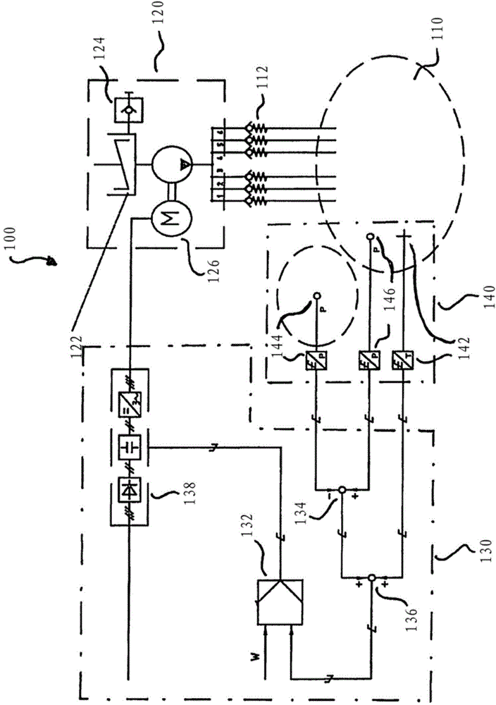
[0018] figure 1 A block diagram of a device 100 for supplying lubricant to a lubrication location 110 in a machine is shown as an example. The device 100 comprises a lubricant pump unit 120 connected to a control unit 130 . The lubricant pump unit 120 supplies lubricant to the lubrication position 110 . The control unit 130 is connected to the lubricant pump unit 120 and regulates the quantity of lubricant supplied by the lubricant pump unit 120 to the lubrication point 110 on the basis of the sensor measurement signals. The sensor measurement signal depends on the measured temperature in the region of the lubrication location 110, the measured pressure in the region of the lubrication location 110, the measured viscosity of the lubricant, the measured dielectric property (or dielectric constant) of the lubricant, The water content of the lubricant is measured, the intensity of the vibrations measured on the parts of the machine and / or the rotational speed measured to the pa...


PUM


Abstract

A device for supplying lubricant to a lubrication point in a machine, a tunnel boring machine, for example, includes a lubrication pump unit and a control unit. The lubrication pump unit is configured to supply a quantity of the lubricant to the lubrication point, and the control unit is configured to regulate the quantity of lubricant based on a sensor measurement signal. The sensor measurement signal may be based on a temperature measured in a region of the lubrication point, a pressure measured in a region of the lubrication point, a measured viscosity of the lubricant, a measured dielectricity of the lubricant, a measured water content of the lubricant, a vibration intensity measured at a part of the machine, or a measured rotational speed of a part of the machine.

Description

technical field [0001] The present embodiment relates to a lubrication system of a machine and in particular a device and a method for supplying lubricant to a lubrication point within a machine. Background technique [0002] Many machines have parts that move relative to each other during operation. In order to minimize possible damage to the parts rubbing against each other, it is often necessary to supply this location with lubricant. Lubricant must be continuously supplied to the lubrication points via the lubrication system during depletion lubrication or recirculation lubrication. Since under-lubrication, ie supply of too little lubricant, needs to be avoided in any case, continuous over-lubrication is used in many cases. This partly results in a loss of lubricant. [0003] It is therefore desirable to provide a technical solution for supplying lubricant to lubrication points within a machine which reduces the consumption of lubricant as much as possible. Contents...

Claims


Application Information

Patent Timeline
Patent Type & Authority Applications(China)
IPC IPC(8): F16N29/02F16N27/00F16N13/00
CPCF16N2250/05F16N2250/36F01M1/16F16N2250/30E21B10/246F16N7/385F16N29/02F16N2250/06F16C33/667F16C19/30F16C2352/00E21D9/1093
Inventor A.波雷克S.弗兰克J.克罗伊兹凯姆珀S.舒尔曼
Owner SKF LUBRICATION SYST GERMANY
Why Eureka
Try Eureka