Vehicle Lamps

A technology for vehicles and lamps, which is applied in the field of high-resolution illumination of specified areas, and can solve problems such as inability to obtain luminosity, inability to effectively illuminate all areas, and insufficient loading

Active Publication Date: 2016-09-28
KOITO MFG CO LTD
View PDF10 Cites 0 Cited by
  • Summary
  • Abstract
  • Description
  • Claims
  • Application Information

AI Technical Summary

Problems solved by technology

[0006] However, in lamps using pixel lamps, due to limitations in light source performance (brightness) and equipment size, it is impossible to obtain the luminosity required for vehicle lamps, especially the luminosity required for high beams
That is, in the lamp structures shown in Patent Documents 1 and 2, as a vehicle lamp, it is not possible to effectively illuminate all areas that need to be illuminated, and the light quantity is insufficient, which is not sufficient for mounting on actual equipment.

Method used


Image

  • Vehicle Lamps
  • Vehicle Lamps
  • Vehicle Lamps

Examples


Embodiment 1

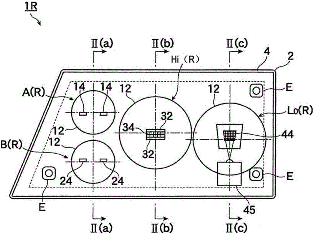
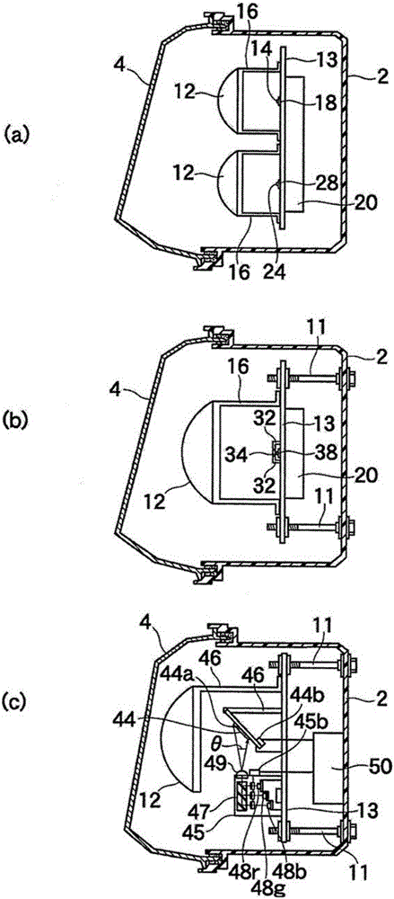
[0034] Hereinafter, preferred embodiments of the present invention will be described with reference to the drawings. figure 1 is a front view of the vehicle lamp according to the first embodiment of the present invention, figure 2 is the longitudinal section view of the lamp, (a) is along the figure 1 Sectional view of line II(a)-II(a), (b) is along figure 1 Section view of line II(b)-II(b), (c) is along figure 1 Sectional view of line II(c)-II(c).

[0035] The vehicle lamps 1R and 1L are vehicle headlamps mounted in a pair of left and right in front of the vehicle. figure 1 The figure shows the lamp 1R arranged on the right side when viewing the vehicle from the front. In addition, in figure 1 In , a light source and the like that cannot be seen when viewing the lamp from the front due to a projection lens and an unillustrated protruding portion (shading plate) are shown in perspective. in addition, Figure 1 ~ Figure 2 The dotted line in is a line passing through the...

Embodiment 2

[0061] In the second embodiment, the low-beam optical unit including the pixel lamp 44 according to the first embodiment is mounted on only one of the lamps 1R and 1L in the first embodiment. As another low beam optical unit, instead of the pixel light optical unit, a projection type LED optical unit is considered as an example. As an example of its structure, it is considered to have the following components: projection lens; LED light source, which is arranged behind the rear focal point on the optical axis of the projection lens, and can emit a predetermined amount of light sufficient for low beam use; reflector, It implements surface aluminum evaporation for reflecting light from the light source toward the projection lens; and a sunshade shielding part of the reflected light from the reflector, the upper end of which is disposed near the optical axis, and is used for low beam The upper end of the light distribution pattern forms a cut-off line.

[0062] According to the ...


PUM


Abstract

A vehicle lamp (1R, 1L) includes a pixel light optical unit (Lo(R), Lo(L)) configured to illuminate a predetermined region (PLo) and an optical unit (H(R), A(R), B(R), H(L), A(L), B(L)) other than the pixel light optical unit (Lo(R), Lo(L)). The optical unit (H(R), A(R), B(R), H(L), A(L), B(L)) is configured to illuminate an upper region (PHi), a right region (PA(R), PB(R)), and a left region (PA(L), PB(L)) of the predetermined region (PLo). A low-beam region (PLo, PB(R), PB(L)) and a high-beam region (PHi, PA(R), PA(L)) are illuminated by combining light of the pixel light optical unit (Lo(R), Lo(L)) and light of the optical unit (H(R), A(R), B(R), H(L), A(L), B(L)).

Description

technical field [0001] The present invention relates to a method for illuminating a defined area with high resolution using a pixel light optical unit [0002] lamps for vehicles. Background technique [0003] As an example of a vehicular lamp using a pixel light optical unit, that is, an optical unit capable of forming a plurality of light distribution patterns at high The device (DMD: Digital Mirror Device) digitally controls the ON / OFF of multiple extremely small mirror elements, so that the light from the light source forms a predetermined light distribution pattern. Patent Document 2 describes a vehicle lamp that uses a liquid crystal shutter (LCD: Liquid Crystal Display) and performs ON / OFF control by changing the orientation of liquid crystal molecules so that light from a light source can be in a predetermined distribution. light pattern. Hereinafter, in the present invention, the so-called pixel light refers to an optical unit capable of changing a light distribu...

Claims


Application Information

Patent Timeline
Patent Type & Authority Patents(China)
IPC IPC(8): F21S8/10F21V13/04F21V14/02F21V23/00F21W101/10F21Y115/10
CPCB60Q1/0041B60Q1/085B60Q2300/056B60Q2300/41B60Q2300/42B60Q2300/45B60Q2400/50F21S41/125F21S41/143F21S41/151F21S41/153F21S41/16F21S41/18F21S41/663F21S41/675
Inventor 小松元弘
Owner KOITO MFG CO LTD
Why Eureka
Try Eureka