Method and system for detecting optical ring resonator resonance frequencies and free spectral range
A technology of resonators and lasers, applied in instruments, measuring devices, surveying and navigation, etc., can solve the problems of cost, size, weight and power loss increase
- Summary
- Abstract
- Description
- Claims
- Application Information
AI Technical Summary
Problems solved by technology
Method used
Image
Examples
example 1
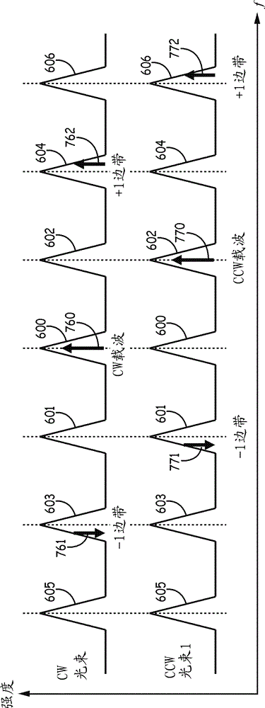
[0095]Example 1 includes a resonator fiber optic gyroscope comprising: a gyroscope resonator having a clockwise input port and a counterclockwise input port and a free spectral range (FSR); a first laser configured to couple a clockwise beam to into the clockwise input port; a clockwise Pound-Drever-Hall modulation generator for modulating the clockwise beam with resonant tracking modulation before the clockwise beam is coupled into the clockwise input port; bias correction electronics; Free Spectral Range (FSR) detection and servo electronics including a switch communicatively coupled to a clockwise Pound-Drever-Hall modulation generator; a clockwise transmission detector configured to receive output from a counterclockwise input port and outputs a signal to the bias correction electronics and FSR detection and servo electronics; and a second laser configured to couple a counterclockwise beam into the counterclockwise input port, where the clockwise beam is based on the Pound-...
example 2
[0096] Example 2 includes the resonator fiber optic gyroscope of Example 1, wherein the bias correction electronics is the first bias correction electronics, the FSR detection and servo electronics is the first FSR detection and servo electronics, and the resonance tracking modulation is the first resonant tracking modulation, and the switch is a first switch, the resonator fiber optic gyroscope also includes: a counterclockwise Pound-Drever-Hall modulation generator that tracks the modulation at a second resonant frequency before the counterclockwise beam is coupled into the counterclockwise input port modulated counterclockwise beam; second bias correction electronics; second FSR detection and servo electronics including a second switch communicatively coupled to the counterclockwise Pound-Drever-Hall modulation generator; and counterclockwise transmission detection is arranged to receive the beam output from the clockwise input port and output a signal to the second bias cor...
example 3
[0097] Example 3 includes the resonator fiber optic gyroscope of Example 2, wherein the first bias correction electronics and the second bias correction electronics comprise: an analog-to-digital converter; a first digital mixer receiving an input from the analog-to-digital converter ; a second digital mixer that receives an input from the first digital mixer; an accumulator that receives an input from the second digital mixer and controls the Pound-Drever-Hall loop lock set point, where the bias error is control to zero average value; and a digital-to-analog converter, wherein the output from the digital-to-analog converter in the first bias correction electronics is input to the clockwise Pound-Drever-Hall servo electronics, and wherein the output from the second bias correction electronics The output of the digital-to-analog converter in the set correction electronics is input to the counterclockwise Pound-Drever-Hall servo electronics.
PUM
 Abstract
Description
Claims
Application Information
 - R&D
- Intellectual Property
- Life Sciences
- Materials
- Tech Scout
- Unparalleled Data Quality
- Higher Quality Content
- 60% Fewer Hallucinations
Browse by: Latest US Patents, China's latest patents, Technical Efficacy Thesaurus, Application Domain, Technology Topic, Popular Technical Reports.
© 2025 PatSnap. All rights reserved.Legal|Privacy policy|Modern Slavery Act Transparency Statement|Sitemap|About US| Contact US: help@patsnap.com


