Substrate electricity leakage test method of switch tube

A technology of substrate leakage and testing methods, which is applied in the directions of measuring electricity, measuring devices, measuring electrical variables, etc., can solve the problems of long testing time and low efficiency.

Active Publication Date: 2014-08-27
CSMC TECH FAB2 CO LTD
View PDF5 Cites 8 Cited by
  • Summary
  • Abstract
  • Description
  • Claims
  • Application Information

AI Technical Summary

Problems solved by technology

[0004] In order to improve the possibility of detecting device abnormalities, the gate voltage is usually gradually increased from 0 volts with a relatively small fixed step s

Method used


Image

  • Substrate electricity leakage test method of switch tube
  • Substrate electricity leakage test method of switch tube
  • Substrate electricity leakage test method of switch tube

Examples


Example Embodiment

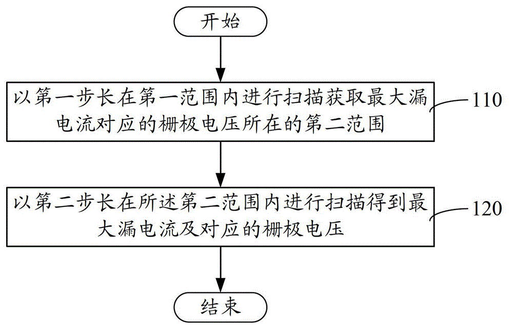
[0035] like figure 1 As shown in FIG. 1 , it is a flow chart of a method for testing substrate leakage of a switch transistor according to an embodiment. The switch tube may be an N-type MOS tube or a P-type MOS tube. The method includes the following steps.

[0036] Step S110: Scanning in the first range with the first step length to obtain the second range where the gate voltage corresponding to the maximum leakage current is located. The first range is the value range of the test voltage applied to the gate of the switch tube, the gate voltage corresponding to the maximum leakage current should fall within the first range, and the first range can be determined based on experience. For example, for most N-type MOS transistors, the gate voltage corresponding to the maximum substrate leakage current is about 1.2 volts. Therefore, the first range can be determined as 0-3 volts. Of course, the value of the first range is not limited thereto, and can be flexibly selected in o...


PUM


Abstract

The invention discloses a substrate electricity leakage test method for a switch tube. The method includes the following steps: adopting a first step length to obtain a second range of a grid voltage corresponding to a maximum leakage current through scanning in a first range; and adopting a second step length to obtain a grid voltage corresponding the maximum leakage current through scanning in the second range, wherein the first step length is larger than the second step length. The test method first adopts a larger first step length to carry out rough scanning so as to reduce a value range of a test voltage and then adopts a second step length which is smaller in step length to carry out fine scanning so as to obtain a grid voltage corresponding to the maximum leakage current. Compared with a method which directly adopts a small step length to carry out a scanning test directly, test times are reduced significantly and the test efficiency is improved.

Description

technical field [0001] The invention relates to component testing technology, in particular to a substrate leakage testing method of a switching tube. Background technique [0002] For the finished components, it is usually necessary to test their reliability. When evaluating the reliability of the switching tube, it is necessary to test whether the maximum leakage current of the substrate or the gate voltage corresponding to the maximum leakage current of the substrate conforms to the working characteristics. [0003] In the traditional test method, the drain of the switching tube is connected to the working voltage, the substrate and the source are connected to zero potential, the gate is continuously selected within a certain test voltage range, and then the substrate current is tested to obtain the maximum value that occurs during the test. The current value is taken as the maximum leakage current of the substrate. [0004] In order to improve the possibility of detect...

Claims


Application Information

Patent Timeline
IPC IPC(8): G01R31/00
Inventor 连晓谦许文慧
Owner CSMC TECH FAB2 CO LTD
Why Eureka
Try Eureka