Wafer suction device and method for parallel device

A wafer and equipment technology, applied in electrical components, semiconductor/solid-state device manufacturing, circuits, etc., can solve the problem of not being able to let go of the wafer, and achieve the effects of easy operation, reducing fragmentation rate, and improving equipment utilization.

Inactive Publication Date: 2014-08-27
SHANGHAI HUALI MICROELECTRONICS CORP
View PDF5 Cites 1 Cited by
  • Summary
  • Abstract
  • Description
  • Claims
  • Application Information

AI Technical Summary

Problems solved by technology

[0007] The present invention solves the problem that the wafer on the suction cup cannot be released because the vacuum pressure at the factory service end is far greater than th

Method used


Image

  • Wafer suction device and method for parallel device
  • Wafer suction device and method for parallel device

Examples


Example Embodiment

[0019] The present invention will be further described below with reference to the drawings and specific embodiments, but it is not a limitation of the present invention.

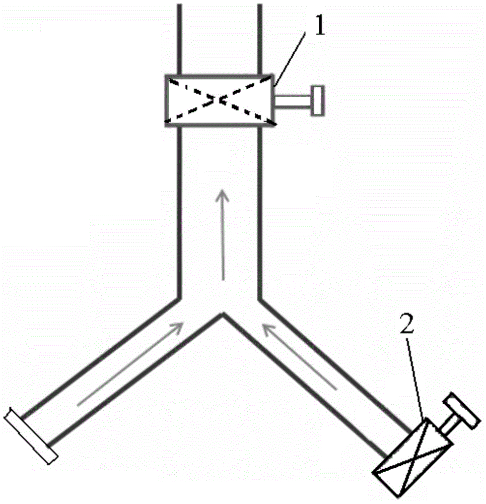
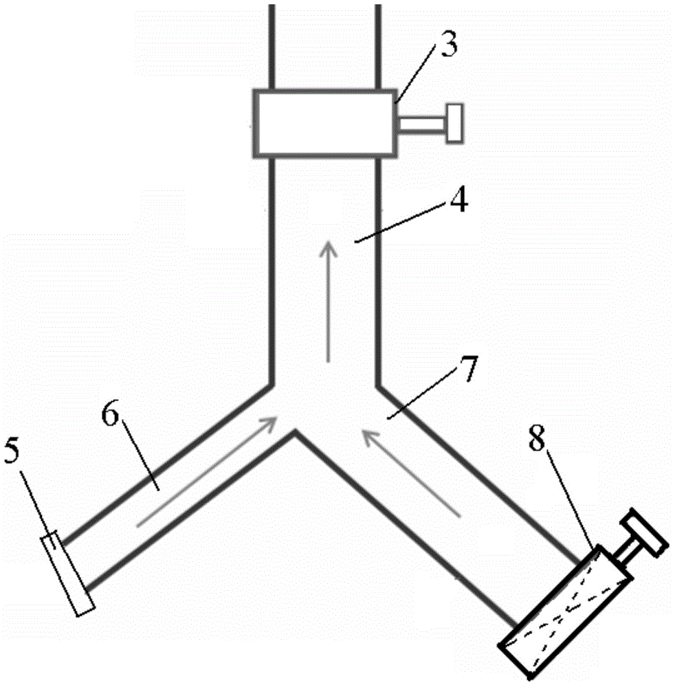
[0020] Such as figure 2 As shown, the present invention provides a wafer adsorption device for parallel equipment, including: factory vacuum pipe 4, equipment vacuum pipe 7, vacuum channel 6, and suction cup 5. The suction cup 5 is arranged at one end of the vacuum channel 6, and the factory vacuum pipe 4. The equipment vacuum pipeline 7 is connected with the vacuum channel 6, and the pipeline diameter of the equipment vacuum pipeline 7 is greater than or equal to the pipeline diameter of the factory vacuum pipeline 4.

[0021] In this embodiment, the diameter of the vacuum pipeline of the equipment is changed, and the purpose of controlling the suction and release of the wafer by the sucker is adopted.

[0022] In a preferred embodiment, it further includes: a first vacuum valve 3, which is arranged on the fact...


PUM


Abstract

The invention discloses a wafer suction device and method for a parallel device, and relates to the field of semiconductors. The wafer suction device comprises a factory service vacuum pipeline, a device vacuum pipeline, a vacuum channel and a suction cup. The suction cup is arranged at one end of the vacuum channel. The factory service vacuum pipeline, the device vacuum pipeline and the vacuum channel are communicated. The pipeline diameter of the device vacuum pipeline is larger than or equal to that of the factory service vacuum pipeline. According to the wafer suction device, the suction cup can suck up and release a wafer by changing the pipeline diameter of the device vacuum pipeline and controlling a second vacuum valve to be opened or closed, a worker can observer the wafer suction and release situation of the suction cup in a close-distance mode through the second vacuum valve, the operation of the worker is facilitated, and therefore the device utilization rate is improved; the second vacuum valve can be repeatedly used and cannot be damaged, and the wafer fragment rate is reduced.

Description

technical field [0001] The invention relates to the field of semiconductors, in particular to a device for absorbing wafers (Wafer) of parallel (Multi site) equipment and a method for absorbing wafers. Background technique [0002] At present, the suction cup (Chuck) in the Multi site equipment is used to pick up and release the wafer manually by manually switching the factory vacuum valve 1 (such as figure 1 As shown), to realize pick-and-place wafer. During the process of picking up and releasing the wafer, the vacuum switch 2 at the equipment end is in an invalid state, and the purpose of absorbing or releasing the wafer is achieved by controlling the factory vacuum valve 1 . The disadvantages of using the method of switching the factory vacuum valve 1 are: because the vacuum pressure at the factory service end is far greater than the equipment manufacturer’s demand for vacuum pressure, the vacuum switch 2 at the equipment end cannot be released when it is turned on. Wa...

Claims


Application Information

Patent Timeline
IPC IPC(8): H01L21/683
CPCH01L21/6838
Inventor 何文蔚
Owner SHANGHAI HUALI MICROELECTRONICS CORP
Why Eureka
Try Eureka