
Sensor synchronization method and sensor measuring system appertaining thereto

A measurement system and sensor technology, applied in the direction of radio wave measurement system, transmission system, digital transmission system, etc., can solve the problem of not providing position value

Active Publication Date: 2014-08-27
HEXAGON TECH CENT GMBH
View PDF7 Cites 16 Cited by
  • Summary
  • Abstract
  • Description
  • Claims
  • Application Information

AI Technical Summary

Problems solved by technology

Moreover, the disadvantage is that, as a result of this direct reference, the provision of the sensor value is not decoupled from the sensor dead time and therefore no additional position value is provided

Method used


Image

  • Sensor synchronization method and sensor measuring system appertaining thereto
  • Sensor synchronization method and sensor measuring system appertaining thereto
  • Sensor synchronization method and sensor measuring system appertaining thereto

Examples


Embodiment Construction

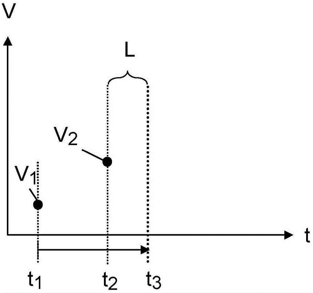
[0069] exist Figure 1a start in Figure 1a -d shows the basic process of synchronous signal generation according to the synchronous method of the present invention. The primary sensor moves forward from the start time at time V 1 at and at a later time V 2 Measure the sensor value V at . Measured value V 1 until the observation time t 3 are available, and the measured value V 2 at time t 3 becomes available everywhere. from V 2 The elapsed time of collection until it is available corresponds to the latency L of the master sensor.

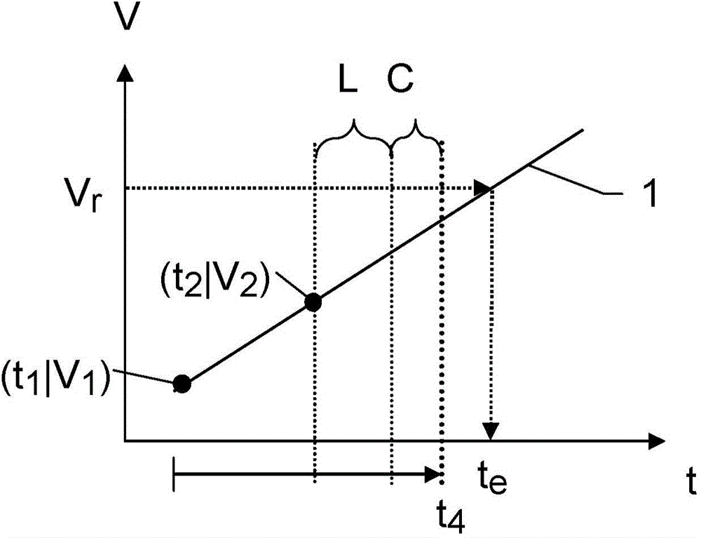
[0070] like Figure 1b As depicted in , the stored parameter values ​​of the extrapolation rules are now calculated and derived from the two available time / measurement pairs (t 1 |V 1 ) and (t 2 |V 2 )supply. In this example, the usage consists of a linear algorithm. If another algorithm, eg based on higher order polynomials, is more convenient, even more time / measurement value pairs are collected and used for parameter value calcul...


PUM


Abstract

The method involves providing extrapolation rule and extrapolated time associated with intended value of a master sensor to be predetermined on basis of the extrapolation rule. A first synchronization signal is transmitted to a slave sensor when the extrapolated time occurs and delay time different from the extrapolated time in a temporally defined manner occurs. Recording of slave sensor value is triggered by a first synchronization signal. The intended value and the slave sensor value are provided as connected value tuple. An independent claim is also included for a sensor measuring system.

Description

technical field [0001] The invention relates to a sensor synchronization method according to the preamble of claim 1 and to a sensor measuring system according to the preamble of claim 13 . Background technique [0002] In measurement systems that include multiple sensors, it is often desirable to collect sensor values ​​from all sensors simultaneously in order to generate a connection data record. For example, if the location of a point object is to be fully determined at a particular time, three corresponding coordinates must be collected simultaneously. [0003] One option for this purpose is to simultaneously transmit a trigger signal to all sensors involved which triggers the collection of measured values ​​of the respective sensor. However, a problem therein is that, in general, not all measurements are collected at a single time due to different types of time delays. For example, delays occur due to different signal runtimes of the trigger signal and measurement sig...

Claims


Application Information

Patent Timeline
Patent Type & Authority Applications(China)
IPC IPC(8): H04L7/00H04W84/18G01S17/08G01S17/87G01S17/89
CPCG01S17/42G01B11/02H04Q9/04H04W56/00G01D18/00G01C25/005G01D5/24495G01S17/87G01S17/89G01S7/003G01S7/497G01B11/002H04J3/0641
Inventor R·菲尔施
Owner HEXAGON TECH CENT GMBH
Learn More