LED linear stepless dimming circuit

A technology of stepless dimming and wiring, applied in the direction of lamp circuit layout, light source, electric light source, etc., can solve the problems of high cost, interference, complicated wiring, etc., and achieve the effect of high production cost, no electromagnetic interference, and uniform dimming process

Inactive Publication Date: 2014-08-27
XINCHANG BORNYOUNG LIGHTING
View PDF3 Cites 1 Cited by
  • Summary
  • Abstract
  • Description
  • Claims
  • Application Information

AI Technical Summary

Problems solved by technology

However, this method is generally realized by a chip or a single-chip microcomputer, and the cost is relatively high, and the circuit is complicated, and there are disadvantages such as EMI electromagnetic interference.

Method used


Image

  • LED linear stepless dimming circuit
  • LED linear stepless dimming circuit

Examples


Embodiment 1

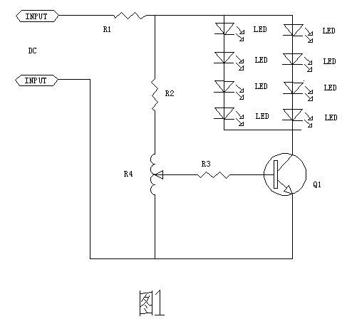
[0014] Such as figure 1 The shown linear stepless dimming circuit for LED includes a constant voltage direct current power supply DC, the constant voltage direct current power supply DC is connected to the first resistor R1 circuit, and the first resistor R1 is connected to the second resistor R2 and the positive pole circuit of the LED respectively. The second resistor R2 is connected to the circuit of the sliding rheostat R4; the cathode of the LED is connected to the collector circuit of the triode Q1, the base of the triode Q1 is connected to the circuit of the third resistor R3, and the third resistor R3 is connected to the circuit of the third resistor R3. The sliding rheostat R4 is connected to the line, and the emitter stage of the triode Q1 is connected in series with the sliding rheostat R4 to the constant voltage direct current power supply DC line.

[0015] The input constant-voltage direct-current power supply DC includes a finished power supply purchased in the m...

Embodiment 2

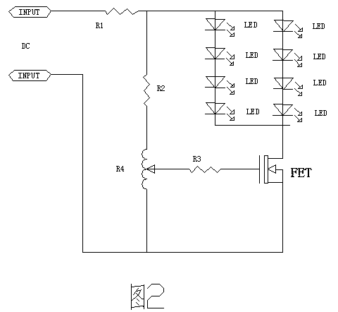
[0019] Such as figure 2 The shown linear stepless dimming circuit for LED includes a constant voltage direct current power supply DC, the constant voltage direct current power supply DC is connected to the first resistor R1 circuit, and the first resistor R1 is connected to the second resistor R2 and the positive pole circuit of the LED respectively. The second resistor R2 is connected to the circuit of the sliding rheostat R4; the negative electrode of the LED is connected to the drain circuit of the field effect transistor FET, and the gate of the field effect transistor FET is connected to the circuit of the third resistor R3, so The third resistor R3 is connected to the line of the sliding rheostat R4, and the source of the field effect transistor FET is connected in series with the sliding rheostat R4 and then connected to the DC line of the constant voltage direct current power supply.

[0020] The input constant-voltage direct-current power supply DC includes a finishe...


PUM


Abstract

The invention discloses an LED linear stepless dimming circuit which comprises a constant-voltage direct-current power source. The constant-voltage direct-current power source is connected with a first resistor through a line. The first resistor is respectively connected with a second resistor and the positive electrode of an LED through lines, the second resistor is connected with a slide rheostat through a line, the negative electrode of the LED is connected with a collector of an audion through a line, a base of the audion is connected with a third resistor through a line, the third resistor is connected with the slide rheostat through a line, an emitter of the audion is connected with the slide rheostat in series and then is connected with the constant-voltage direct-current power source through a line, and at least one LED is installed between the first resistor and the collector of the audion. The LED linear stepless dimming circuit is even in dimming process, free of strobing and electromagnetic interference, efficient and low in production cost.

Description

technical field [0001] The invention relates to a dimming circuit, in particular to an LED linear stepless dimming circuit. Background technique [0002] At present, LED dimming technology mainly realizes the controllability of the power of LED lights by controlling the frequency or conduction time of the switching tube, and completes the control of luminous flux of 0-100% of the brightness of the lights. However, this method is generally realized by a chip or a single-chip microcomputer, and the cost is relatively high, and the circuit is complicated, and there are disadvantages such as EMI electromagnetic interference. Contents of the invention [0003] The object of the present invention is to provide an LED linear stepless dimming circuit, which has simple design, uniform dimming process, no flicker, no electromagnetic interference, high efficiency and low production cost. [0004] In order to achieve the above object, technical scheme of the present invention is: ...

Claims


Application Information

Patent Timeline
Patent Type & Authority Applications(China)
IPC IPC(8): H05B37/02
Inventor 廖崇文
Owner XINCHANG BORNYOUNG LIGHTING
Why Eureka
Try Eureka