Nozzle device

A nozzle device, nozzle hole technology, applied in the direction of spray device, spray device, spray device with movable outlet, etc., to achieve the effect of simple structure

Active Publication Date: 2014-09-03
KSK
View PDF5 Cites 18 Cited by
  • Summary
  • Abstract
  • Description
  • Claims
  • Application Information

AI Technical Summary

Problems solved by technology

[0008] However, in the fire extinguishing nozzle device described in Patent Document 1, since the inclination angle of the peripheral nozzle cylinder is fixed, the spray angle is fixed, and it is impossible to match the spray area to the area to be extinguished without changing the position where the fire extinguishing operation is performed. ground change

Method used


Image

  • Nozzle device
  • Nozzle device
  • Nozzle device

Examples


Embodiment 1)

[0229] (Structure of Nozzle Unit)

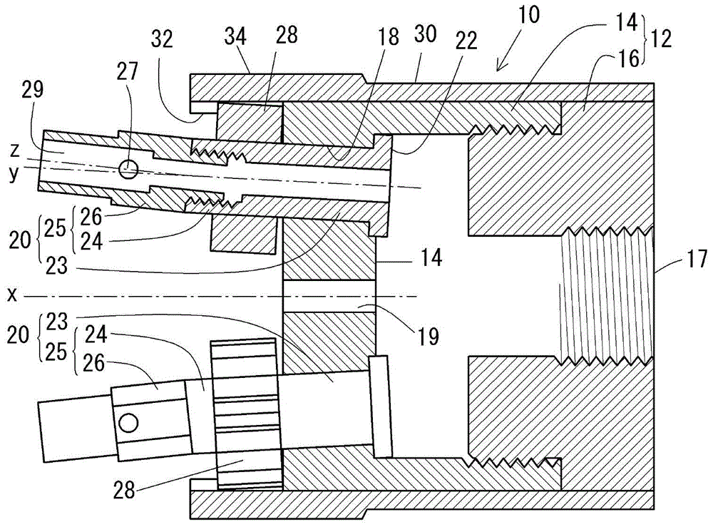
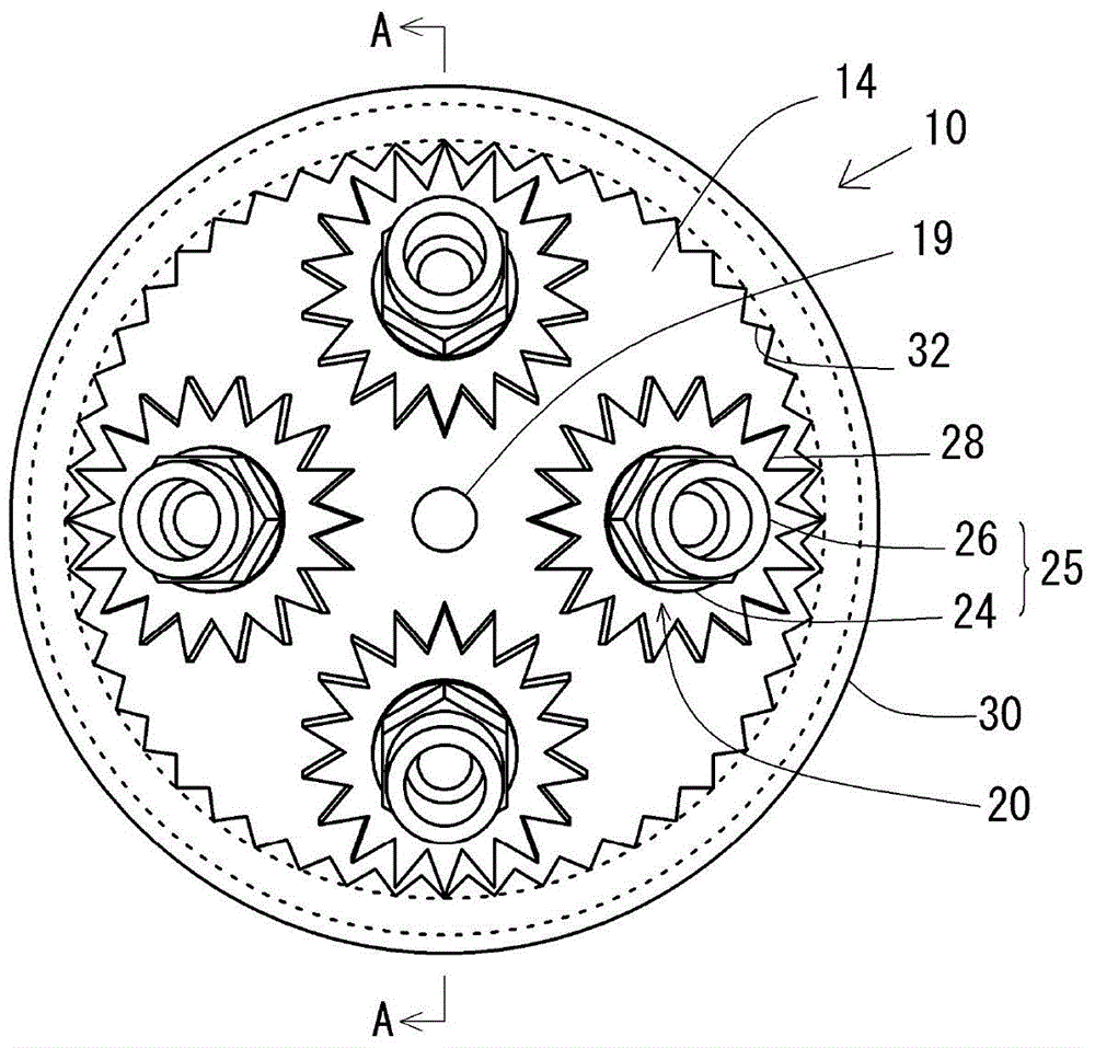
[0230] exist figure 1 The structure of the nozzle device 10 according to the first embodiment of the present invention is shown by a part of cross-section. The nozzle device 10 is a multi-port nozzle for fire extinguishing, and has a base body 12 , a rotary nozzle 20 and a rotary ring 30 . The rotary ring 30 corresponds to the control means of the present invention.

[0231] The base body 12 is a hollow member formed by integrating a cylindrical nozzle holding portion 14 with the same outer diameter and a water supply pipe connection portion 16 by screwing together. In the nozzle device 10 , the axis of the base body 12 coincides with the axis of the nozzle device 10 , and the radial direction of the base body 12 is the same as the radial direction of the nozzle device 10 . In the axial direction of the nozzle device 10, the side of the nozzle holder 14 is called the spray side, the side of the water supply pipe connection 16 is called t...

Embodiment 2)

[0263] exist Figure 5 The structure of the nozzle apparatus 10b of Example 2 of this invention is shown by a part of cross section in the figure. In the nozzle device 10b, like the nozzle device 10, four rotating nozzles 20b are arranged on the same circumference. exist Figure 5 In , the description of the rear rotary nozzle 20b and the like is omitted. In the nozzle device 10b, the injection hole 18b formed in the nozzle holder 14b of the base body 12b has a conical shape expanding toward the water supply side, and the base end portion 23b of the rotary nozzle 20b inscribed with the injection hole 18b also expands toward the water supply side. hollow conical shape. The seat part is not provided in the end part of the water supply side of the base end part 23b. Since the structure of the other parts of the nozzle device 10b is the same as that of the nozzle device 10 of the first embodiment, the same or corresponding symbols are assigned and descriptions thereof are omitte...

Embodiment 3)

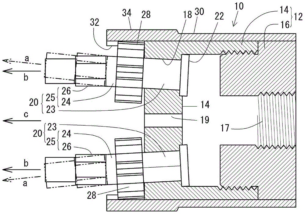
[0266] exist Figure 6 The structure of the nozzle apparatus 10c which concerns on Example 3 of this invention is shown by a part of cross section in the middle. In the nozzle device 10c, like the nozzle device 10, four rotating nozzles 20c are arranged on the same circumference. exist Figure 6 In , the description of the rear rotary nozzle 20c and the like is omitted.

[0267] In the nozzle device 10 of Embodiment 1, the axis of the injection hole 18 is inclined at 3 degrees toward the injection side and radially outward of the nozzle device 10 with respect to the axis of the nozzle device 10, while in the nozzle device 10c of Embodiment 3, a The axis of the injection hole 18c in the nozzle holder 14c of the base body 12c is parallel to the axis of the nozzle device 10c. Furthermore, the rotation axis y of the base end portion 23c of the rotary nozzle 20c rotatably inserted through the injection hole 18c is also parallel to the axis x of the nozzle device 10c, and the noz...


PUM


Abstract

The present invention provides a nozzle device (10) comprising: a solid cylindrical body member (12) in which a supply opening (17) and nozzle insertion holes (18) are formed; hollow rotatable nozzles (20) which are rotatably inserted through the nozzle insertion holes (18) and which protrude to the discharge side; and a hollow cylindrical rotatable ring (30) which is rotatably fitted over the outside of the body member (12). The axis (z) of a hole in the front end of the protrusion (25) of each of the rotatable nozzles (20) is tilted relative to the axis (y) of the base section (23) of the rotatable nozzle (20), the base section (23) being internally in contact with the nozzle insertion hole (18). Rotation transmission mechanisms (28, 32) which transmit the rotation of the rotatable ring (30) to the rotatable nozzles (20) are provided to the base sections (24) of the rotatable nozzles (20) and to the inner peripheral surface of the rotatable ring (30). As a result of this configuration, rotating the rotatable ring (30) enables a change in the angle of discharge of liquid which is discharged from the nozzle device.

Description

technical field [0001] The present invention relates to nozzle devices. More specifically, it relates to a nozzle device capable of spraying liquid such as water and continuously changing the angle at which the liquid is sprayed. Background technique [0002] As a nozzle device for ejecting liquid such as water, there are known a single nozzle that ejects water straightly with a single port, and a shower nozzle that ejects water in a shower or spray form through a plurality of fine holes. [0003] Single-port nozzles are widely used for long-distance spraying because of their strong pressure and destructive power, but they cannot perform wide spraying. Shower nozzles, on the other hand, are used for diffuse sprays, which give a wide spray with less pressure and are used for shampooing or gardening, but have a shorter range. [0004] Even if it is a single-port nozzle, there are nozzles that can switch the spray state to mist, diffuse, shower, jet, etc. by moving the pin in...

Claims


Application Information

Patent Timeline
Patent Type & Authority Applications(China)
IPC IPC(8): B05B1/14B05B3/02B05B15/68
CPCB05B3/12A62C31/05B05B15/08B05B1/14B05B15/68B05B3/026B05B15/652B05B1/02B05B1/08
Inventor 楠伸治
Owner KSK
Why Eureka
Try Eureka