Pipe fitting punching machine

A technology for punching machines and pipe fittings, applied in the field of machinery, can solve the problems of difficulty in guaranteeing punching precision, easy deformation of mandrels, short service life of pipe punching devices, etc., and achieves high punching precision, high production efficiency and reasonable structure. Effect

Inactive Publication Date: 2014-09-03
JIAXING VOCATIONAL TECHN COLLEGE
View PDF8 Cites 6 Cited by
  • Summary
  • Abstract
  • Description
  • Claims
  • Application Information

AI Technical Summary

Problems solved by technology

[0004] Although the pipe punching device disclosed in this patent can process holes of various shapes on the pipe wall of a long pipe, the pipe punching device only uses a mandrel to position the pipe, and the mandrel is easily deformed, resulting in poor punching accuracy. It is difficult to guarantee, and the service life of the pipe punching device is short, so it is necessary to design a pipe punching machine

Method used


Image

  • Pipe fitting punching machine
  • Pipe fitting punching machine
  • Pipe fitting punching machine

Examples


Embodiment Construction

[0031] The following are specific embodiments of the present invention and in conjunction with the accompanying drawings, the technical solutions of the present invention are further described, but the present invention is not limited to these embodiments.

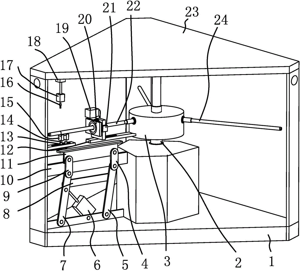
[0032] Such as figure 1 As shown, the pipe fitting drilling machine includes a base 1, on which a driving shaft 2 is fixed axially and rotated in a circumferential direction, and a lower bearing seat is fixed on the base 1, and the lower bearing seat is fixed by bolt connection On the base 1; the lower bearing seat is provided with a lower bearing, the lower end of the drive shaft 2 is pierced and fixed on the inner ring of the lower bearing, and the cooperation between the inner ring of the lower bearing and the lower end of the drive shaft 2 is a transition fit; above the base 1 A positioning plate 23 is provided, and the positioning plate 23 is fixed on the base 1 through the connecting bracket 10. The upper bearing sea...


PUM


Abstract

The invention provides a pipe fitting punching machine, and belongs to the technical field of machines. The pipe fitting punching machine solves the technical problems that due to the fact that an existing pipe punching device only positions a pipe with a core rod which is prone to deformation, the punching precision is low. The pipe fitting punching machine comprises a base. A driving shaft is arranged on the base in an axial-fixing and circumferential-rotation mode. A positioning plate is arranged above the base and fixed to the base through a connecting support. The driving shaft is connected with a power mechanism which can drive the driving shaft to rotate. A rotating disc is fixedly arranged in the middle of the driving shaft. A core rod with which a pipe fitting is sleeved is fixedly arranged on the rotating disc. A supporting device is arranged at the lower portion of the other end of the core rod. A plurality of through holes are formed in the core rod. The core rod is further sleeved with a positioning device which can position the pipe fitting to the core rod. A punching device is further arranged at the lower portion of the positioning plate. The punching device comprises a drill bit which can be located over the through holes of the core rod. The pipe fitting punching machine has the advantages of being high in punching efficiency and high in mechanical degree.

Description

technical field [0001] The invention belongs to the technical field of machinery, and relates to a punching machine, in particular to a punching machine for pipe fittings. Background technique [0002] During the drilling process of pipe fittings, the pipe fittings are generally placed on a mandrel with one end suspended in the air, and then the drilling process is carried out; because one end of the mandrel fixing the pipe fittings is suspended in the air, its bearing capacity is poor. It is difficult to guarantee the punching accuracy in the process. [0003] After searching, a pipe punching device [patent number: ZL200910208278.7; authorized announcement number: CN101708520B] is disclosed in the Chinese patent literature. This pipe punching device includes a frame and a workbench installed on the frame. A punching device is installed on the workbench. A pipe clamping device and a material unloading device that cooperate with the punching device are installed on the workb...

Claims


Application Information

Patent Timeline
IPC IPC(8): B26F1/16B26D7/02B26D5/08B26D7/00
Inventor 任立威
Owner JIAXING VOCATIONAL TECHN COLLEGE
Why Eureka
Try Eureka