A polysilicon reduction furnace chassis and tail gas cooling system and method thereof
A technology of exhaust gas cooling and chassis cooling, applied in chemical instruments and methods, silicon compounds, inorganic chemistry, etc., can solve problems such as waste and no recycling, and achieve the effect of saving resources, high value of by-products, and increasing benefits
- Summary
- Abstract
- Description
- Claims
- Application Information
AI Technical Summary
Problems solved by technology
Method used
Image
Examples
Embodiment 1
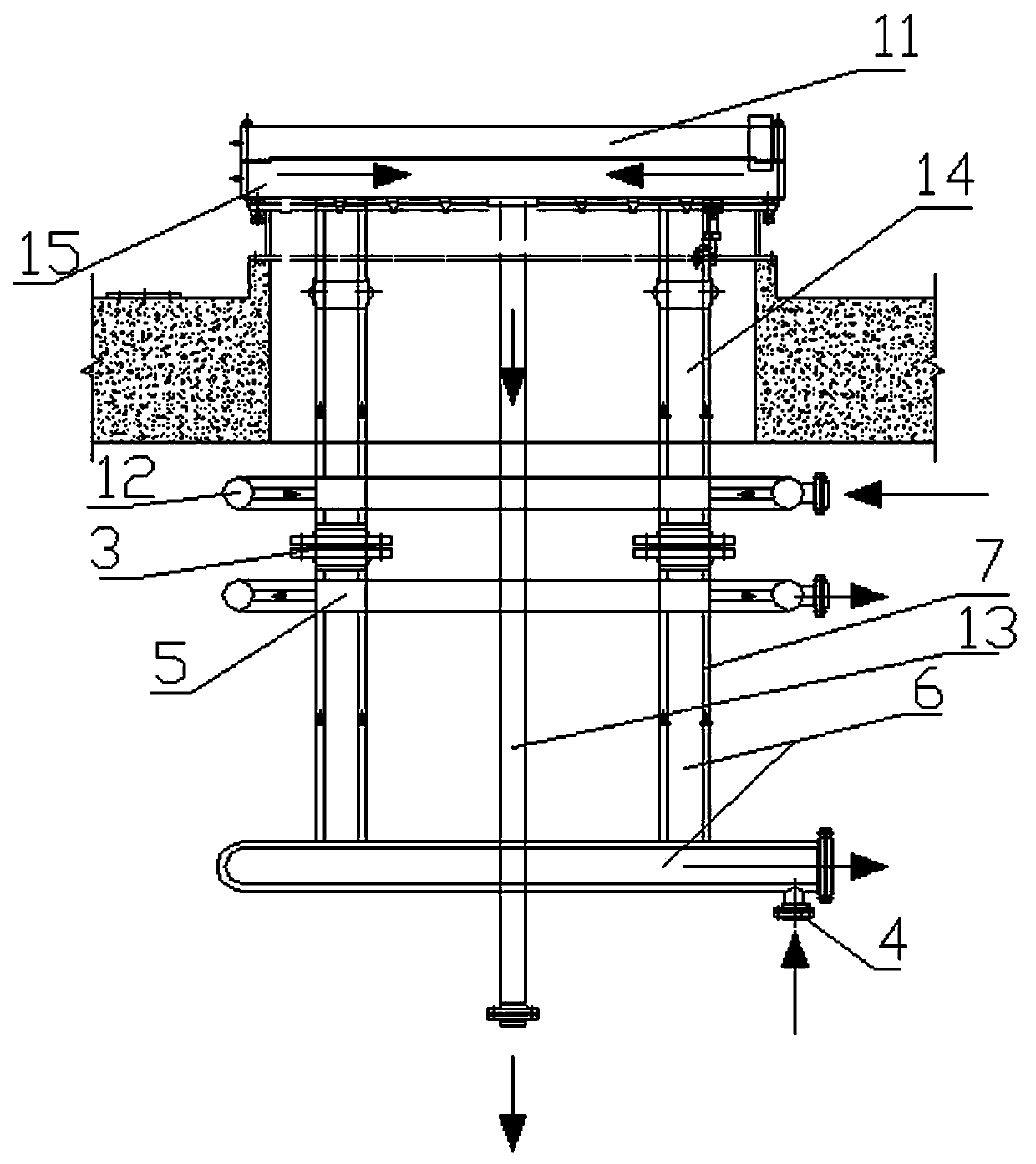
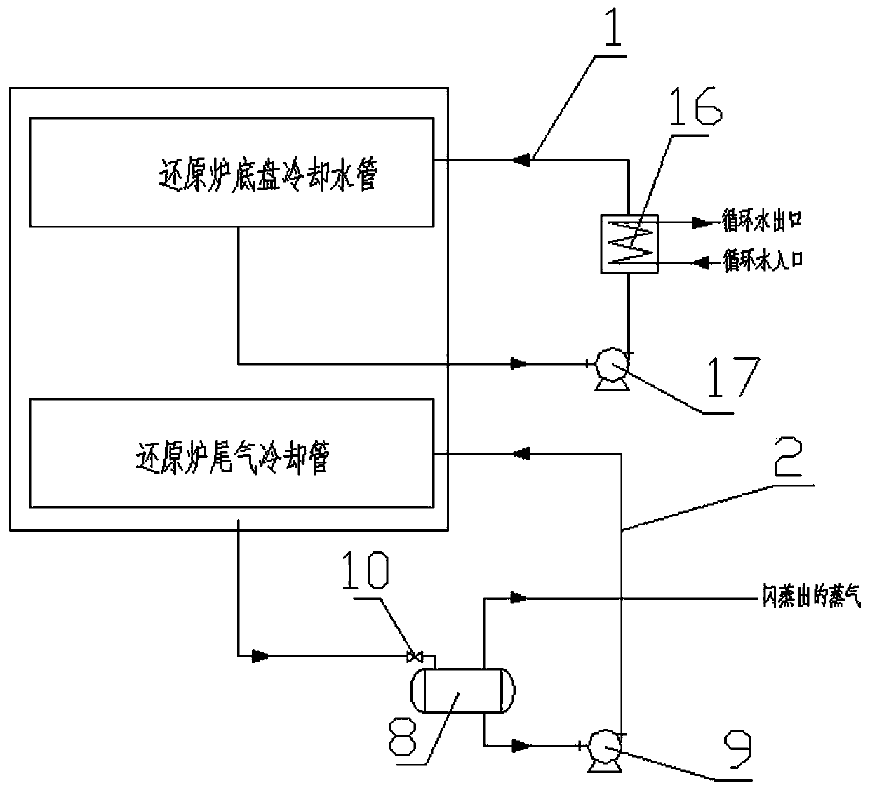
[0026] As a preferred embodiment of the present invention, with reference to the attached figure 1 with 2 , the present invention includes a reduction furnace chassis cooling structure 1 and an exhaust gas cooling structure 2, the reduction furnace chassis cooling structure 1 and the exhaust gas cooling structure 2 are connected through a flange 3; the exhaust gas cooling structure 2 includes an exhaust gas cooling water inlet 4, Exhaust gas cooling water outlet pipe 5 and exhaust gas exhaust pipe 6, said exhaust gas exhaust pipe 6 is provided with interlayer casing 7, said exhaust cooling water inlet 4 is arranged on the interlayer casing 7 at the lower end of exhaust gas exhaust pipe 6, The exhaust cooling water outlet pipe 5 is arranged on the upper end of the exhaust pipe 6 and communicates with the interlayer casing 7 on the exhaust pipe 6 . The tail gas cooling structure 2 also includes a flash tank 8 and a tail gas cooling water circulation pump 9, the flash tank 8 is ...
Embodiment 2
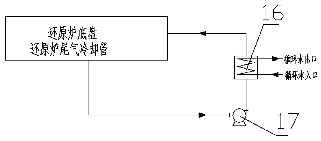
[0029] As another preferred embodiment of the present invention, refer to the attached figure 1 with 2 , the present invention includes a reduction furnace chassis cooling structure 1 and an exhaust gas cooling structure 2, the reduction furnace chassis cooling structure 1 and the exhaust gas cooling structure 2 are connected through a flange 3; the exhaust gas cooling structure 2 includes an exhaust gas cooling water inlet 4, Exhaust gas cooling water outlet pipe 5 and exhaust gas exhaust pipe 6, said exhaust gas exhaust pipe 6 is provided with interlayer casing 7, said exhaust cooling water inlet 4 is arranged on the interlayer casing 7 at the lower end of exhaust gas exhaust pipe 6, The exhaust cooling water outlet pipe 5 is arranged on the upper end of the exhaust pipe 6 and communicates with the interlayer casing 7 on the exhaust pipe 6 . The tail gas cooling structure 2 also includes a flash tank 8 and a tail gas cooling water circulation pump 9, the flash tank 8 is pro...
Embodiment 3
[0034] As another preferred embodiment of the present invention, with reference to the attached figure 1 with 2 , the present invention includes a reduction furnace chassis cooling structure 1 and an exhaust gas cooling structure 2, the reduction furnace chassis cooling structure 1 and the exhaust gas cooling structure 2 are connected through a flange 3; the exhaust gas cooling structure 2 includes an exhaust gas cooling water inlet 4, Exhaust gas cooling water outlet pipe 5 and exhaust gas exhaust pipe 6, said exhaust gas exhaust pipe 6 is provided with interlayer casing 7, said exhaust cooling water inlet 4 is arranged on the interlayer casing 7 at the lower end of exhaust gas exhaust pipe 6, The exhaust cooling water outlet pipe 5 is arranged on the upper end of the exhaust pipe 6 and communicates with the interlayer casing 7 on the exhaust pipe 6 . The tail gas cooling structure 2 also includes a flash tank 8 and a tail gas cooling water circulation pump 9, the flash tank...
PUM
 Abstract
Description
Claims
Application Information
 - R&D
- Intellectual Property
- Life Sciences
- Materials
- Tech Scout
- Unparalleled Data Quality
- Higher Quality Content
- 60% Fewer Hallucinations
Browse by: Latest US Patents, China's latest patents, Technical Efficacy Thesaurus, Application Domain, Technology Topic, Popular Technical Reports.
© 2025 PatSnap. All rights reserved.Legal|Privacy policy|Modern Slavery Act Transparency Statement|Sitemap|About US| Contact US: help@patsnap.com


