

Water-saving faucet
A faucet and faucet technology, applied in valve details, lift valves, engine components, etc., can solve problems such as unstable performance, inability to open delay settings for water-saving devices, and failure of delay settings to prevent water resources. The effect of wasting and saving the waiting time for water injection
- Summary
- Abstract
- Description
- Claims
- Application Information
AI Technical Summary
Problems solved by technology
Method used
Image

Examples
Embodiment 1
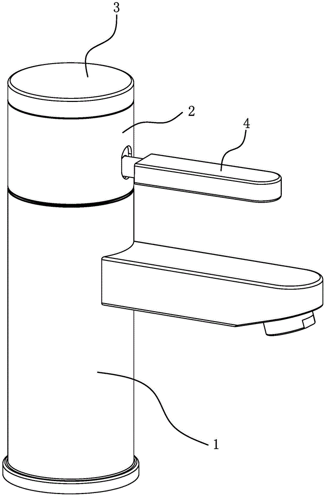
[0033] Such as figure 1 As shown, the water-saving faucet includes a faucet body 1 , a jacket 2 , an adjustment handwheel 3 and a handle 4 . The jacket 2 is located between the faucet main body 1 and the adjustment hand wheel 3 , and the jacket 2 is provided with a relief hole for the handle 4 to be pulled, and the handle 4 is inserted into the jacket 2 .
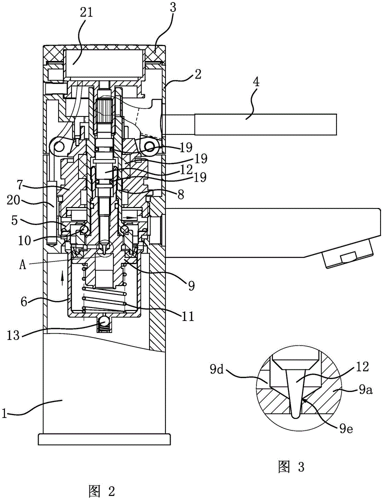
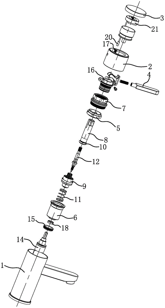
[0034] Such as figure 2 As shown, the main body of the faucet 1 is provided with a water diversion core 5, a water storage cylinder 6 and a fixing seat 7, the water storage cylinder 6 is located below the water diversion core 5, the fixing seat 7 is located above the water diversion core 5, and the fixing seat 7 It is connected with the main body of the faucet 1 through threads, and then the water diversion core 5 and the water storage cylinder 6 are both fixedly connected with the main body of the faucet 1 . The outer casing 2 is fixedly connected with the fixing seat 7 through bolts 17 .
[0035] The water diversion cor...
Embodiment 2
[0044] The structure and principle of this embodiment are basically the same as that of Embodiment 1, the difference is that: Figure 4 and Figure 5 As shown, the water-saving faucet also has a temperature adjustment function. A temperature control valve core 14 is provided in the faucet main body 1. The temperature control valve core 14 is located at the bottom of the faucet main body 1 and is fixed on the faucet main body 1 through a pressure cap 15. The water outlet of the control valve core 14 communicates with the water inlet channel 1a of the faucet body 1 .
[0045] The valve rod 14a of the temperature control valve core 14 penetrates into the water storage cylinder 6 and the base 9a of the movable core assembly 9, and the valve rod 14a is connected with the base 9a by a spline. The base 9a of the movable core assembly 9 penetrates the pull rod 8, and the base 9a and the pull rod 8 are connected by splines.
[0046] The pull rod 8 is covered with a rotating seat 16 ,...
Embodiment 3
[0054] The structure and principle of this embodiment are basically the same as that of Embodiment 1 or Embodiment 2. The difference is that the adjustment structure includes a small water hole located in the movable core assembly 9 and connected to the inner cavity of the water storage cylinder 6 and the water inlet channel 1a. 9d and the ceramic valve core 10, the adjustment rod 12 is axially positioned and connected with the movable core assembly 9, and the end of the adjustment rod 12 is connected with the ceramic valve core 10.
PUM
 Abstract
Description
Claims
Application Information