Anti-explosion LED (light emitting diode) lamp with strong heat dissipation performance
A technology of explosion-proof lamps and LED chips, which is applied in the field of lighting, can solve problems such as complex heat dissipation structures, and achieve the effects of simple heat dissipation structures, enhanced heat exchange capabilities, and reduced intermediate components
- Summary
- Abstract
- Description
- Claims
- Application Information
AI Technical Summary
Problems solved by technology
Method used
Image
Examples
Embodiment 1
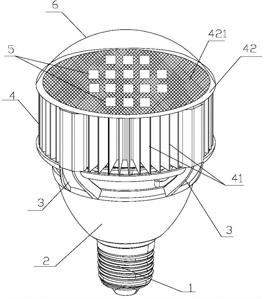
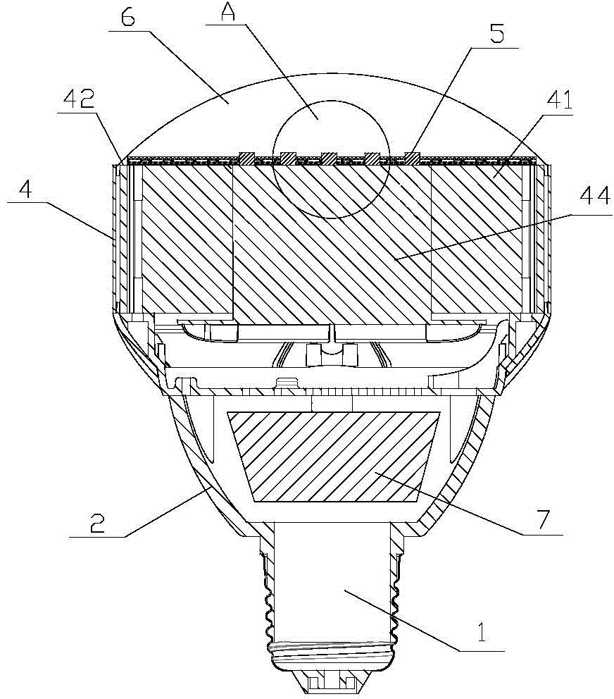
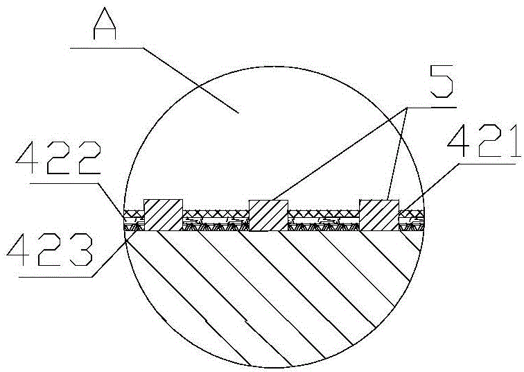
[0026] The strong heat dissipation LED explosion-proof lamps and lanterns in this embodiment, such as Figure 1 to Figure 3 As shown, a power supply 7 is placed in the sealed power supply chamber 2, one end of the power supply chamber 2 is connected to the lamp holder 1, and the other end is connected to the radiator 4 through the connection part 3, and the distance between the heat source of the LED light source and the heat source of the power supply is increased through the connection part 3, further separating them. heat source, to prevent heat sources from interfering with each other. The middle part of the heat sink 4 is a solid main body 44, and the periphery of the solid main body 44 is provided with a plurality of heat dissipation fins 41. The LED chip 5 is directly packaged on the top surface 42 of the heat sink 4, and there is no need to set a chip packaging base, and the edge of the top surface 42 is installed. With the lampshade 6, the heat of the LED chip 5 is co...
Embodiment 2
[0030] The strong heat dissipation LED explosion-proof lamps and lanterns in this embodiment, such as Figure 4 to Figure 6 As shown, a power supply 7 is placed in the sealed power supply chamber 2, one end of the power supply chamber 2 is connected to the lamp holder 1, and the other end is connected to the radiator 8 through the connecting part 3, and the distance between the heat source of the LED light source and the heat source of the power supply is increased through the connecting part 3, further separating them. heat source, to prevent heat sources from interfering with each other. The middle part of the heat sink 8 is a hollow structure 83, and the LED chip 5 is directly packaged on the top surface 82 of the heat sink 8 without a chip packaging base. The top surface 82 of the radiator 8 conducts from the top surface 82 to the hollow structure 83 of the radiator 8, and exchanges heat with the surrounding air through the body wall 85 of the radiator 8, and the heat diss...
Embodiment 3
[0034] This embodiment is basically the same as Embodiments 1 and 2, the only difference being: Figure 7 and Figure 8 As shown, the upper end of the radiator 4 or the radiator 8 is close to the bottom of the LED chip 5 and is provided with a heat conduction cavity 9, and the heat conduction cavity 9 is equipped with a heat conduction liquid 10, and the heat conduction cavity 9 arranged close to the bottom surface of the LED chip 5 is equipped with a heat conduction liquid 10, each The heat generated by the LED chip 5 is rapidly conducted in all the heat-conducting liquids 10, and the temperature of each LED chip 5 is balanced, so that the operating temperature of each LED chip 5 is basically the same, which is conducive to the uniform light emission of each LED chip 5, and when the heat-conducting liquid 10 is heated Circular convection is formed in the heat conduction cavity 9, which strengthens the heat exchange capability between the LED chip 5 and the heat sink 4 or 8, a...
PUM
 Abstract
Description
Claims
Application Information
 - R&D
- Intellectual Property
- Life Sciences
- Materials
- Tech Scout
- Unparalleled Data Quality
- Higher Quality Content
- 60% Fewer Hallucinations
Browse by: Latest US Patents, China's latest patents, Technical Efficacy Thesaurus, Application Domain, Technology Topic, Popular Technical Reports.
© 2025 PatSnap. All rights reserved.Legal|Privacy policy|Modern Slavery Act Transparency Statement|Sitemap|About US| Contact US: help@patsnap.com


