Plate structure impact load positioning method based on distributed fiber bragg grating sensing network

A distributed optical fiber and grating sensing technology, applied in the direction of optical devices, measuring devices, instruments, etc., can solve the problems of poor generalization performance, easy to be affected by temperature changes, poor practicability and real-time performance, etc.

Active Publication Date: 2014-09-03
NANJING UNIV OF AERONAUTICS & ASTRONAUTICS
View PDF4 Cites 27 Cited by
  • Summary
  • Abstract
  • Description
  • Claims
  • Application Information

AI Technical Summary

Problems solved by technology

However, the shortcomings of this method require a large number of different impact situations to train the network, the generalization

Method used


Image

  • Plate structure impact load positioning method based on distributed fiber bragg grating sensing network
  • Plate structure impact load positioning method based on distributed fiber bragg grating sensing network
  • Plate structure impact load positioning method based on distributed fiber bragg grating sensing network

Examples


Embodiment Construction

[0051] Below in conjunction with specific embodiment, further illustrate the present invention, should be understood that these embodiments are only used in the present invention and are not intended to limit the scope of the present invention, after reading the present invention, those skilled in the art can modify various equivalent forms of the present invention All fall within the scope defined by the appended claims of this application.

[0052] The flow chart of the plate structure impact load location method based on the distributed fiber grating sensor network is shown in Fig. Figure 4 As shown, the specific implementation steps are as follows:

[0053] Step 1: Distributed optical fiber sensor network layout

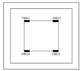
[0054] Such as figure 1 As shown, four fiber optic FBG sensors are arranged symmetrically in a square shape in the specimen structure, the fiber optic FBG sensors are pasted on the back of the specimen structure, and the four fiber optic FBG sensors are serial...


PUM


Abstract

The invention provides a plate structure impact load positioning method based on a distributed fiber bragg grating sensing network, and belongs to the field of impact monitoring of structure firmness monitoring. The method includes the steps of firstly, arranging the distributed fiber bragg grating sensing network; secondly, collecting an impact response signal; thirdly, extracting feature information and analyzing sensitive characteristics of an FBG sensor; fourthly, positioning the position of an impact point through the association algorithm of the maximum peak amplitude ratio of the impact response signal and position information. The positioning algorithm is simple, rapid, convenient and reliable and is high in instantaneity.

Description

technical field [0001] The invention belongs to the field of impact monitoring of structural health monitoring, and specifically proposes a plate structure impact load positioning method based on a distributed optical fiber grating sensor network. Background technique [0002] The earliest shock location identification method is to calculate the location information of the shock by extracting the arrival time of the shock stress wave, and according to the relationship among distance, time, and stress wave velocity. However, in actual situations, the extraction of the time of arrival of the stress wave is greatly affected by noise. In 1997, Gaul and Hurlebaus used wavelet transform to process the shock response signal, which reduced the influence of noise and accurately extracted the time of arrival , for distance, multiple times. The wave velocity equation is optimized to obtain the location information of the shock. In 2005, Meo et al. applied this method to the impact lo...

Claims


Application Information

Patent Timeline
IPC IPC(8): G01B11/00
Inventor 曾捷张先辉曹亮史璐刘苏州毛超群
Owner NANJING UNIV OF AERONAUTICS & ASTRONAUTICS
Why Eureka
Try Eureka