Two-dimension self-calibration gauge point detection alignment system

A technology for aligning systems and marking points, applied in measuring devices, instruments, optical devices, etc., can solve the problems of long self-calibration process, high working environment requirements, low signal acquisition frequency, etc., to improve the self-calibration effect. , the effect of reducing deficiencies and low environmental sensitivity

Active Publication Date: 2014-09-03
TSINGHUA UNIV +1
View PDF8 Cites 8 Cited by
  • Summary
  • Abstract
  • Description
  • Claims
  • Application Information

AI Technical Summary

Problems solved by technology

However, there are obvious disadvantages and shortcomings in this scheme. Due to the limitation of the optical diffraction limit, the highest alignment accuracy is only about 100nm, which greatly affects the final self-calibration effect; secondly, due to the use of optical The microscope cooperates with the image sensor as a detection system, which involves a large number of image data processing problems, resulting in a low frequency of signal acquisition. In this case, only static alignment can be performed, and it is difficult to align and calibrate during the movement of the workbench. This largely leads to long self-calibration process and low efficiency; moreover, due to the use of optical microscopes and image sensors and other equipment, it is bound to bring about high cost and high system complexity; and this scheme will be subject to certain Environmental impact, so the requirements for the working environment are relatively high

Method used


Image

  • Two-dimension self-calibration gauge point detection alignment system
  • Two-dimension self-calibration gauge point detection alignment system
  • Two-dimension self-calibration gauge point detection alignment system

Examples


Embodiment Construction

[0022] The structure, principle and specific implementation of the present invention will be further described in detail below in conjunction with the accompanying drawings.

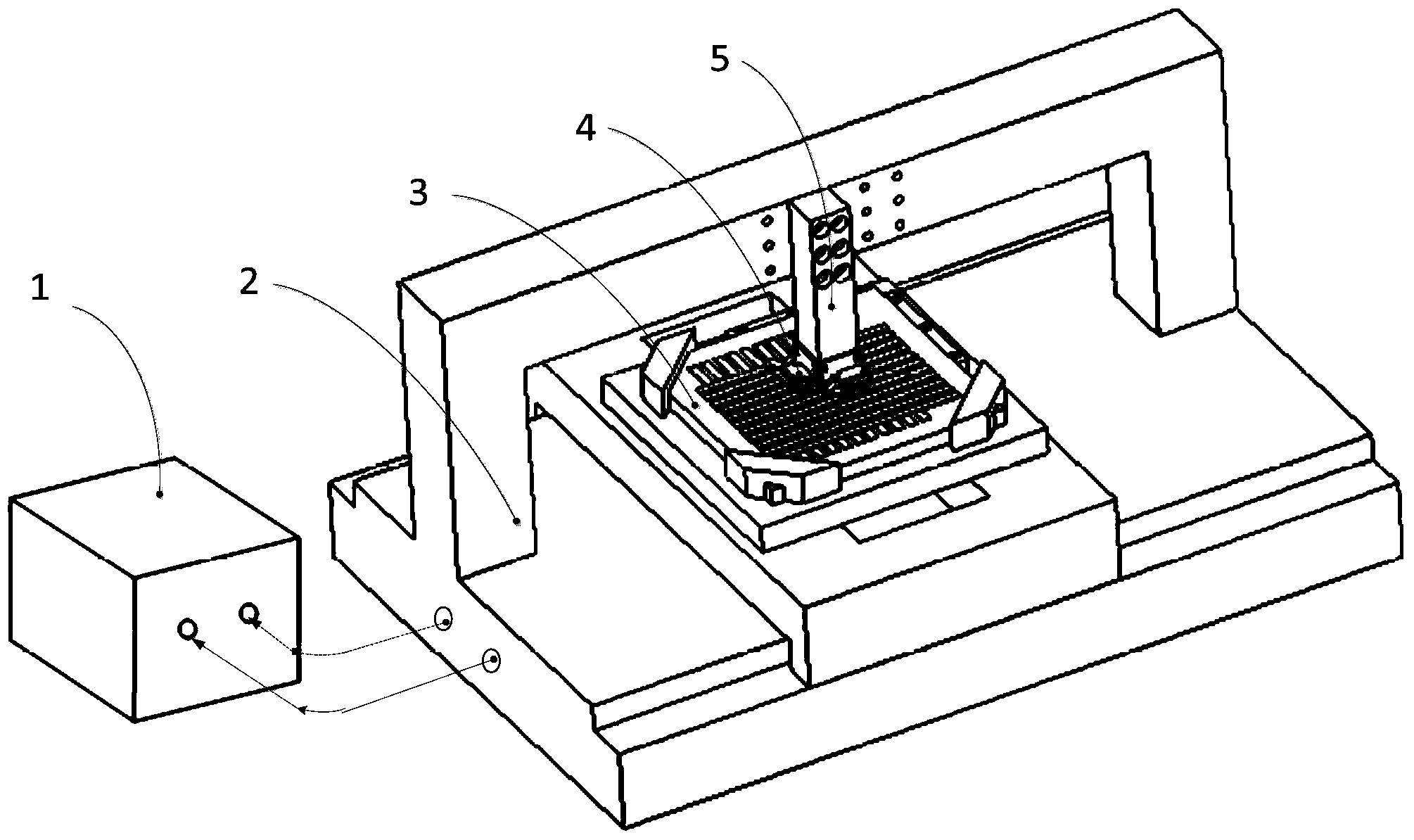
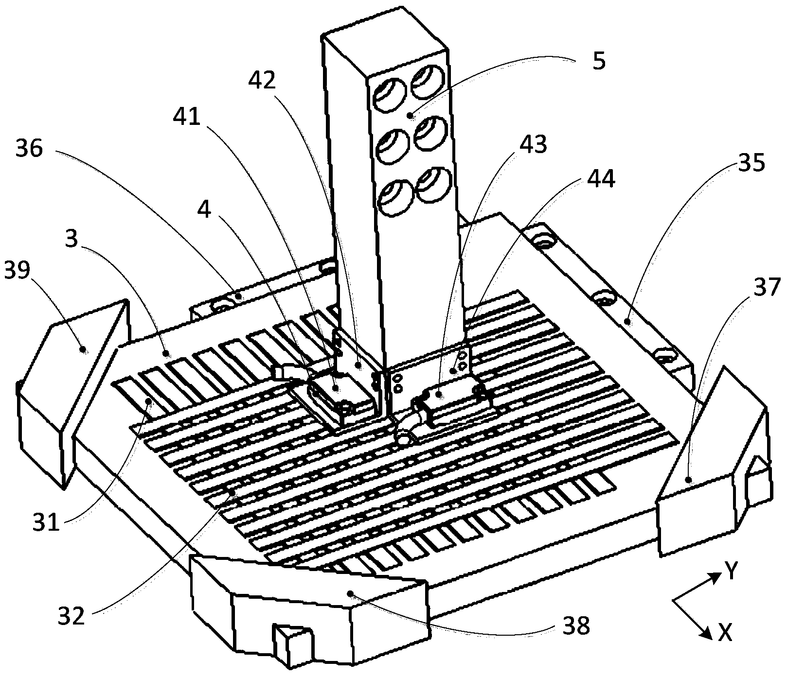
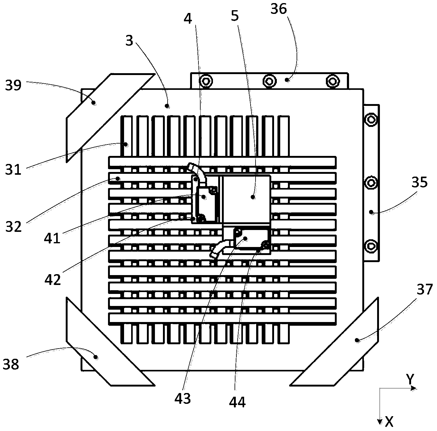
[0023] Please refer to figure 1 , figure 1 It is a schematic diagram of a two-dimensional self-calibration mark point detection and alignment system of the present invention. Such as figure 1 As shown, the two-dimensional self-calibration mark point detection and alignment system includes: a zero signal reader 1, a two-dimensional workbench 2, a grating ruler auxiliary calibration plate 3, a reading head detection part 4, and a measurement reference frame 5;

[0024] The zero signal reader 1 and the two-dimensional workbench 2 are connected to each other through signal lines; the grating ruler auxiliary calibration plate 3 includes: X direction channel 33, Y direction channel 34, marked with a zero mark point X-direction grating ruler 31, Y-direction grating ruler 32 marked with zero mark point, first...


PUM


Abstract

A two-dimension self-calibration gauge point detection alignment system comprises a zero signal reader, a two-dimension workbench, a grating ruler auxiliary calibration plate, a reading head detection part and a measuring reference frame. The grating ruler auxiliary calibration plate comprises grating rulers with zero gauge points in the X direction and in the Y direction. The reading head detection part comprises a grating ruler reading head and a mounting support. The alignment system achieves gauge point alignment based on a grating ruler detection alignment principle and a zero signal detection principle. The reading head detects zero gauge point signals on the grating ruler auxiliary calibration plate to transmit the signals to the zero signal reader, meanwhile, the two-dimension workbench records the position coordinates of the two-dimension workbench and transmits the signals to the zero signal reader, and the position coordinates of the zero gauge points are obtained. The two-dimension self-calibration gauge point detection alignment system can be applied to the two-dimension self-calibration technology, and nanoscale resolution and alignment precision are achieved. Signal reading time delay is small, and the two-dimension self-calibration gauge point detection alignment system can be applied to workbench dynamic and high-speed calibration. The entire structure is relatively simple, the performance is high, and the two-dimension self-calibration gauge point detection alignment system is not sensitive to environments.

Description

technical field [0001] The invention relates to a detection and alignment system, in particular to a two-dimensional self-calibration mark point detection and alignment system. Background technique [0002] The application of ultra-precision worktables in the field of precision engineering is becoming more and more extensive, and the measurement accuracy requirements for multi-dimensional workbenches are also getting higher and higher. In the field of ultra-precision processing (such as high-end lithography machines), the multi-dimensional measurement accuracy often needs to reach nanometers level or even sub-nanometer level. The development of self-calibration technology has brought new solutions to the calibration problems of ultra-precision workbench measurement systems. Among them, the self-calibration method is based on the use of an auxiliary measuring device whose accuracy of the marking point is lower than that of the object being calibrated as a medium. Through the...

Claims


Application Information

Patent Timeline
Patent Type & Authority Applications(China)
IPC IPC(8): G01B11/00
Inventor 朱煜胡楚雄徐振源张鸣杨进穆海华胡金春徐登峰尹文生杨开明刘召成荣
Owner TSINGHUA UNIV
Why Eureka
Try Eureka