Method for measuring Bohr resonance phase difference and modifying data through continuous photographing or camera shooting

A Bohr resonance and camera measurement technology, which is applied in the field of physical experiment parameter measurement, can solve problems such as reduction of flash, insufficient partial pressure of experimental instruments, abnormal working status of electronic circuits of measuring instruments, etc., to achieve the effect of expanding thinking ability and avoiding influence

Inactive Publication Date: 2014-09-03
SICHUAN UNIV
View PDF3 Cites 1 Cited by
  • Summary
  • Abstract
  • Description
  • Claims
  • Application Information

AI Technical Summary

Problems solved by technology

[0007] Due to the high current of the flash lamp, the internal partial voltage of the experimental instrument is insufficient when the flash lamp is used, which may cause abnormal working status of the electronic circuit of the measuring instrument. It has been found in the experiment that the displayed cycle data has abnormal changes, usually when the flash occurs. The significant reduction has caused many students to question: Is the phase difference data accurate?

Method used


Image

  • Method for measuring Bohr resonance phase difference and modifying data through continuous photographing or camera shooting
  • Method for measuring Bohr resonance phase difference and modifying data through continuous photographing or camera shooting
  • Method for measuring Bohr resonance phase difference and modifying data through continuous photographing or camera shooting

Examples


Embodiment Construction

[0012] Using continuous photography or video to measure Bohr resonance phase difference and data correction method, the steps are:

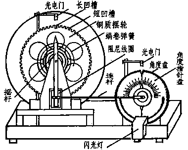
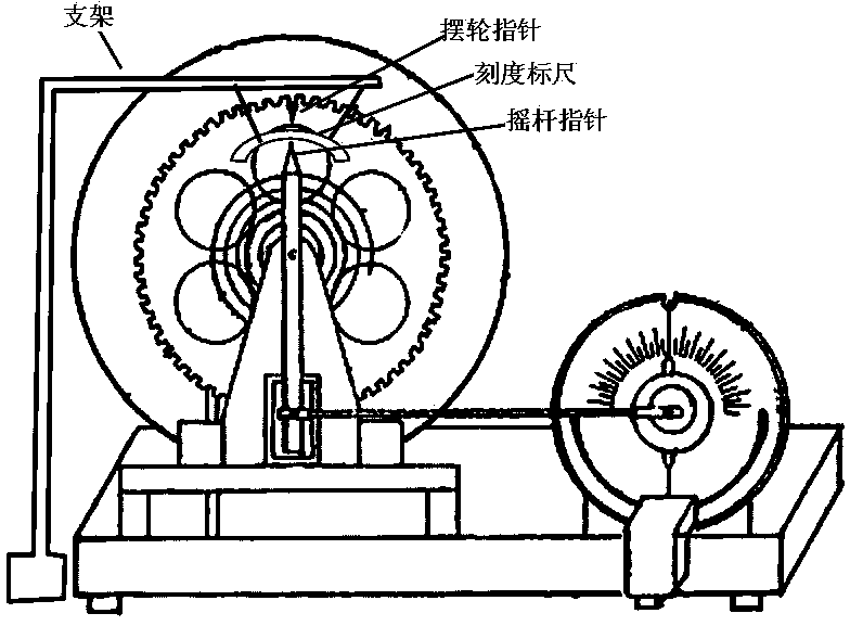
[0013] Step 1: Hang a scale between the balance wheel and the rocker through the bracket. The suspension line is a hard metal wire, and the hard metal wire is fixed on the bracket by screw threads, so that the position of the suspended scale is constant and will not be affected. Influenced by the gas flow generated by the movement of the balance wheel, the scale is arc-shaped, and its center coincides with the center of the balance wheel and the swing center of the rocker. There are scales on the scale, and the scales are angles;

[0014] It should be further explained that the center of the balance wheel of the existing instrument coincides with the swing center of the rocker (the fixed point of the rocker). The adjustment of the center of the scale circle can be accomplished by moving and lifting the bracket. When the Bohr resonance instrument ...


PUM


Abstract

The invention discloses a method for measuring Bohr resonance phase difference and modifying data through continuous photographing or camera shooting, relates to the field of physical experiment parameter measurement, and discloses an experiment method which takes the place of a method for measuring phase difference by stroboflash. According to the technical scheme, a scale ruler is suspended between a balance wheel and a rocker, wherein the scale ruler takes the shape of an arc with angle scales; a balance wheel pointer is fixed on the balance wheel; when Bohr resonance forced vibration is in a stable state, the relationship between the balance wheel and the rocker in Bohr resonance forced vibration is recorded through continuous photographing or camera shooting; the time difference delta T generated when the balance wheel pointer and a rocker pointer point to one same scale on the scale ruler, and the swinging period T are confirmed through a computer according to the photographing time of a picture or the time interval of frames of camera shooting, and the phase difference is 360o*delta T / T; linear interpolation is adopted for modifying data when the balance wheel pointer and the rocker pointer cannot point to one same scale. The method has the beneficial effects that the influence of large current on the working state of an electronic circuit is avoided, and the method is an improvement of the prior art.

Description

technical field [0001] The invention relates to the field of physical experiment parameter measurement, in particular to the measurement of the phase difference between an external force and a balance wheel when a Bohr resonance instrument is forced to vibrate. Background technique [0002] In the university physics laboratory, the Bohr resonance instrument generally uses the stroboscopic method to measure the phase difference between the external force and the balance wheel. The experimental device is as follows: figure 1 . [0003] Device structure: the angle disc is fixed on the outside of the motor. The angle disc is not connected with the motor shaft and is in a static state, that is, it does not rotate with the motor shaft. The angle disc and the motor shaft have a common center of circle. The upper semicircle of the angle disc has a scale. The minimum scale is 1 degree; the outside of the angle disc is the angle pointer disc, which is a plastic disc, and the angle po...

Claims


Application Information

Patent Timeline
IPC IPC(8): G01C11/02G09B23/06
CPCG01H9/00G09B23/06
Inventor 胡再国雍志华张俊峰梁雅庭邹旭敏穆万军朱俊饶大庆罗明蓉李娟程艳王维果刘石丹李伟于白茹梁小冲李紫源
Owner SICHUAN UNIV
Why Eureka
Try Eureka