
Real-time recording device for multi-channel data in radar test and method for realizing real-time data recording

A real-time recording and data technology, applied in the direction of radio wave measurement systems, instruments, etc., can solve the problem of lack of real-time recording devices for communication data, achieve the effect of uploading storage and communication data, and avoid storage confusion

Active Publication Date: 2016-07-13
HARBIN INST OF TECH
View PDF5 Cites 0 Cited by
  • Summary
  • Abstract
  • Description
  • Claims
  • Application Information

AI Technical Summary

Problems solved by technology

[0004] The present invention is to solve the problem of lack of real-time recording device for communication data in the existing radar test

Method used


Image

  • Real-time recording device for multi-channel data in radar test and method for realizing real-time data recording
  • Real-time recording device for multi-channel data in radar test and method for realizing real-time data recording

Examples


specific Embodiment approach 1

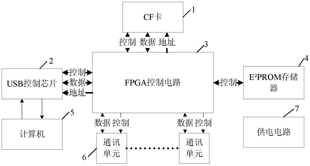
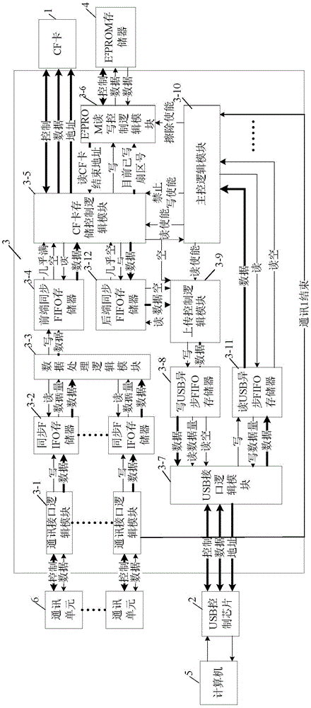
[0018] Specific implementation mode 1: refer to figure 1 and figure 2 Specifically illustrate this embodiment, the real-time recording device of multi-channel data in the radar test described in this embodiment, it comprises CF card 1, USB control chip 2, E 2 PROM memory 4 and n communication units 6, n is a positive integer, it also includes FPGA control circuit 3,

[0019] The FPGA control circuit 3 includes n communication interface logic modules 3-1, data processing logic modules 3-3, CF card storage control logic modules 3-5, E 2 PROM read and write control logic module 3-6, main control logic module 3-10, upload control logic module 3-9, USB interface logic module 3-7, n-way synchronous FIFO memory 3-2, front-end synchronous FIFO memory 3-4 , back-end synchronous FIFO memory 3-12, write USB asynchronous FIFO memory 3-8 and read USB asynchronous FIFO memory 3-11,

[0020] The control signal output or input end of each communication unit 6 is connected to the control s...

specific Embodiment approach 2

[0023] Specific embodiment two: the difference between this embodiment and the real-time recording device of multi-channel data in the radar test described in specific embodiment one is that the communication mode of each communication unit 6 is serial communication, parallel communication, simplex or one of the duplexes.

specific Embodiment approach 3

[0024] Specific embodiment three: the difference between this embodiment and the real-time recording device of multi-channel data in the radar test described in specific embodiment one is that it also includes a computer 5 and a power supply circuit 7,

[0025] The control signal input end of the USB control chip 2 is connected to the control signal output end of the computer 5, and the data signal output end of the USB control chip 2 is connected to the data signal input end of the computer 5,

[0026] The power supply circuit 7 is used to provide power supply for the whole device.


PUM


Abstract

The invention discloses a device for recording multipath data in a radar test in real time and a method for realizing the real-time recording of the data, relating to the field of measurement and control. The invention solves the problem that the existing radar test is lack of a device for recording communication data in real time. An FPGA (Field Programmable Gate Array) control circuit of the device comprises n communication interface logic modules, a data processing logic module, a CF (Compact Flash) card storage control logic module, an E2PROM (Electrical 2 Programmable Read Only Memory) read-write control logic module, a main control logic module, an uploading control logic module, a USB (Universal Serial Bus) interface logic module, n paths of synchronization FIFO (First Input First Output) memories, a front end synchronization FIFO memory, a rear end synchronization FIFO memory, a write USB asynchronization FIFO memory and a read USB asynchronization FIFO memory. The device ensures that different data are orderly stored in a CF card, and prevents the storage from being confused; and a final sector number of valid data in the CF card is detected through the E2PROM memory to ensure that the data is accurately read, and a chip is controlled to upload the data by controlling a USB.

Description

technical field [0001] The invention relates to a method for recording multi-channel data in real time. It belongs to the field of measurement and control. Background technique [0002] Radar is often used as a missile-borne sensor and is installed at the end of the missile. When testing the radar, the test equipment needs to communicate with the inertial navigation system to analyze the environmental information sent by it; it also needs to simulate the function of the missile-borne flight controller, send control commands to the radar, and read and analyze the radar information in time Response to control commands; in addition, when the radar requires GPS guidance, the test equipment also needs to read data from GPS, and so on. [0003] Whether the communication data is correct or not is directly related to whether the whole test system can work normally. In order to be able to conduct a comprehensive detection of the radar, it is necessary to record the communication d...

Claims


Application Information

Patent Timeline
Patent Type & Authority Patents(China)
IPC IPC(8): G01S7/40
CPCG01S7/40
Inventor 付宁赵浩然施睿乔立岩
Owner HARBIN INST OF TECH
Learn More