
TTI (Transmission Time Interval) binding method for reducing business delaying in TD-LTE (Time Division-Long Term Evolution) system

A service delay, cell edge technology, applied in the direction of using the return channel for error prevention/detection, etc., can solve the problems of excessive uplink authorization control signaling overhead, low system throughput, difficulty in meeting service quality requirements, etc., to reduce RV The effect of waiting time, reducing service transmission delay, and improving system throughput

Active Publication Date: 2014-09-03
TIANJIN UNIV
View PDF4 Cites 20 Cited by
  • Summary
  • Abstract
  • Description
  • Claims
  • Application Information

AI Technical Summary

Problems solved by technology

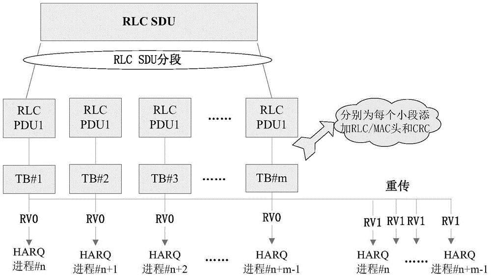
But the following disadvantages are: additional RLC / MAC header overhead, excessive uplink grant control signaling overhead and high HARQ feedback error rate
Obviously, it is difficult for some delay-sensitive services to meet their quality of service requirements through the existing TTI bundling method, and there are low spectrum utilization and system throughput caused by decoding feedback after receiving 4 RVs every time Low volume and other issues

Method used


Image

  • TTI (Transmission Time Interval) binding method for reducing business delaying in TD-LTE (Time Division-Long Term Evolution) system
  • TTI (Transmission Time Interval) binding method for reducing business delaying in TD-LTE (Time Division-Long Term Evolution) system
  • TTI (Transmission Time Interval) binding method for reducing business delaying in TD-LTE (Time Division-Long Term Evolution) system

Examples


Embodiment Construction

[0020] The embodiments of the present invention will be further described in detail below in conjunction with the accompanying drawings.

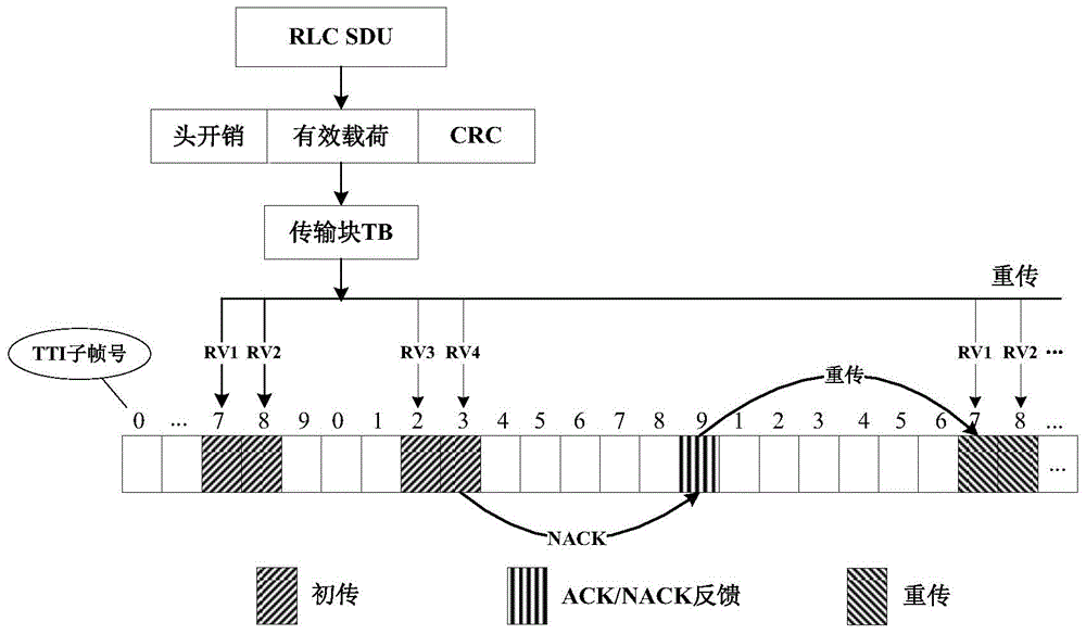
[0021] The invention is figure 2 On the basis of the traditional TTI bundling scheme in the TD-LTE system shown, taking into account the small data packets or high-quality transmission of the UE configured with the bundling function, a TTI bundling method for reducing service delay in the TD-LTE system is proposed. Determine the method.

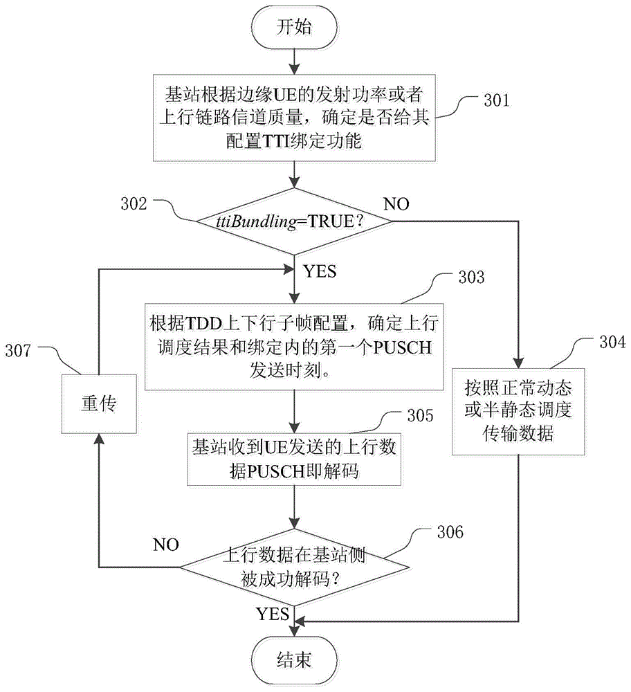
[0022] image 3 It is an implementation flowchart of a TTI binding method for reducing service delay in a TD-LTE system of the present invention, comprising the following steps:

[0023] Step 301: the base station determines whether to configure the TTI bundling function for the edge user according to the continuously received transmission power headroom reported by the cell edge user UE or the detected uplink channel quality of the UE;

[0024] Step 302: judge the value of the ttiBundling parameter in...


PUM


Abstract

The invention discloses a TTI (Transmission Time Interval) binding method for reducing business delaying in a TD-LTE (Time Division-Long Term Evolution) system. The TTI binding method comprises the following steps: utilizing a base station to determine whether a TTI binding function is configured to an edge user or not according to a continuously-received transmitting power margin reported by cell edge user UE (Unified Equipment) or detected uplink chain channel quality of the UE; determining an uplink dispatching result and a bound first physical uplink sharing channel (PUSCH) sending moment according to configuration of TDD (Time Division Duplex) uplink and downlink sub-frames, and a uplink authorization and data sending time relation; otherwise, carrying out data transmission according to normal dynamic or semi-static dispatching; continuously sending different RVs of the same TB to the base station by the cell edge UE with the binding function through a physical uplink sharing channel (PUSCH); after receiving the data, carrying out decoding processing on the data by the base station no matter whether the four RV exist in a caching region or not; judging whether the uplink data is successfully decoded at the base station side or not; if so, finishing the operation; otherwise, carrying out retransmission operation on the data. According to the TTI binding method, unnecessary RV waiting time can be greatly shortened so that the business transmission delaying of the TD-LTE system is reduced and the spectral efficiency and the system throughput are improved.

Description

technical field [0001] The invention relates to the field of wireless communication, in particular to a TTI binding method for reducing service delay in a Time Division Duplex Long Term Evolution (TD-LTE) system. Background technique [0002] TD-LTE is a Time Division Duplex (TDD) version of LTE technology. The main difference from FDD-LTE is that the system uses the same frequency band to transmit uplink and downlink data in different time slots. However, due to the limited transmit power of the UE itself, especially for some services with high delay performance requirements, such as the VoIP service of the UE, the data sent by the UE at the cell edge may not meet the acceptable quality of service (QoS) requirements, making The problem of limited uplink coverage has become a bottleneck to improve system performance. [0003] In response to the above-mentioned problems, Susitaival R et al. pointed out two existing solutions in "LTE coverage improvement by TTI bundling": RLC...

Claims


Application Information

Patent Timeline
Patent Type & Authority Applications(China)
IPC IPC(8): H04L1/16
Inventor 苏寒松李园园刘高华李婷
Owner TIANJIN UNIV
Learn More