
Chuck for machine tool for machining tubular, rotating workpiece

A chuck and workpiece technology, which is applied to the chuck field of machine tools for processing tubular and rotating workpieces, can solve the problems of large diameter and length of the chuck, and achieve the effect of compact structure type

Active Publication Date: 2014-09-03
SMS MEER
View PDF6 Cites 17 Cited by
  • Summary
  • Abstract
  • Description
  • Claims
  • Application Information

AI Technical Summary

Problems solved by technology

This results in a larger diameter and length of the chuck with a correspondingly larger mass which is disadvantageous for operation

Method used


Image

  • Chuck for machine tool for machining tubular, rotating workpiece
  • Chuck for machine tool for machining tubular, rotating workpiece
  • Chuck for machine tool for machining tubular, rotating workpiece

Examples


Embodiment Construction

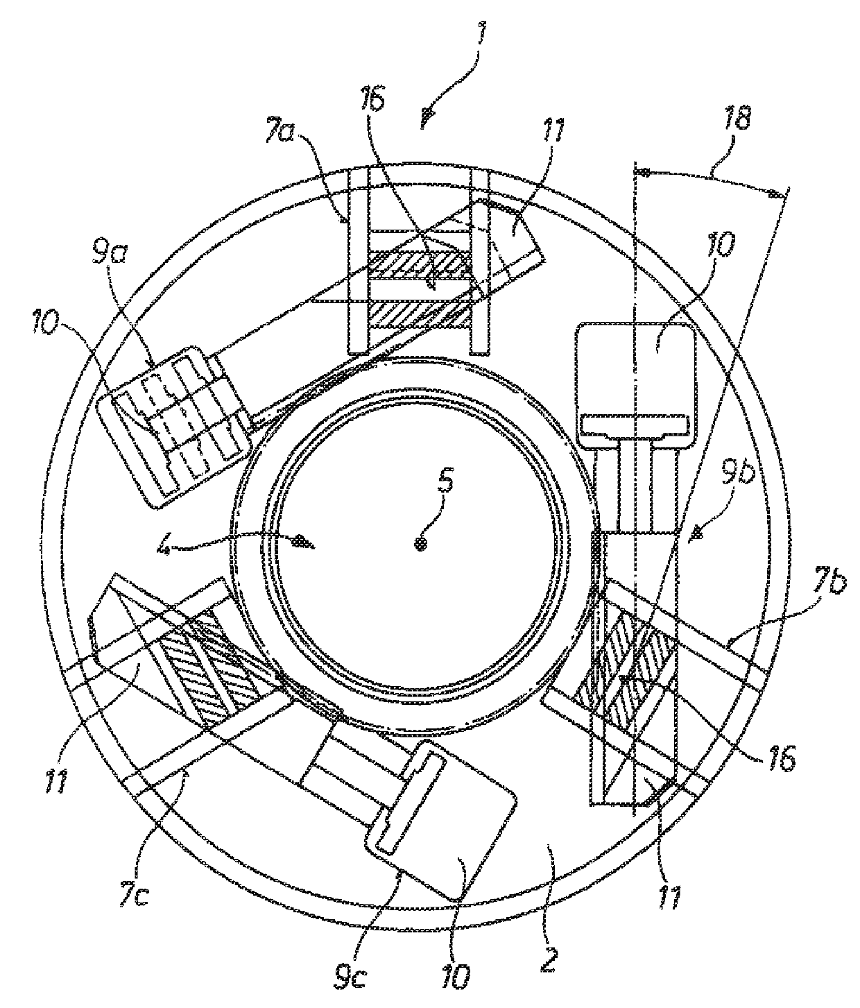
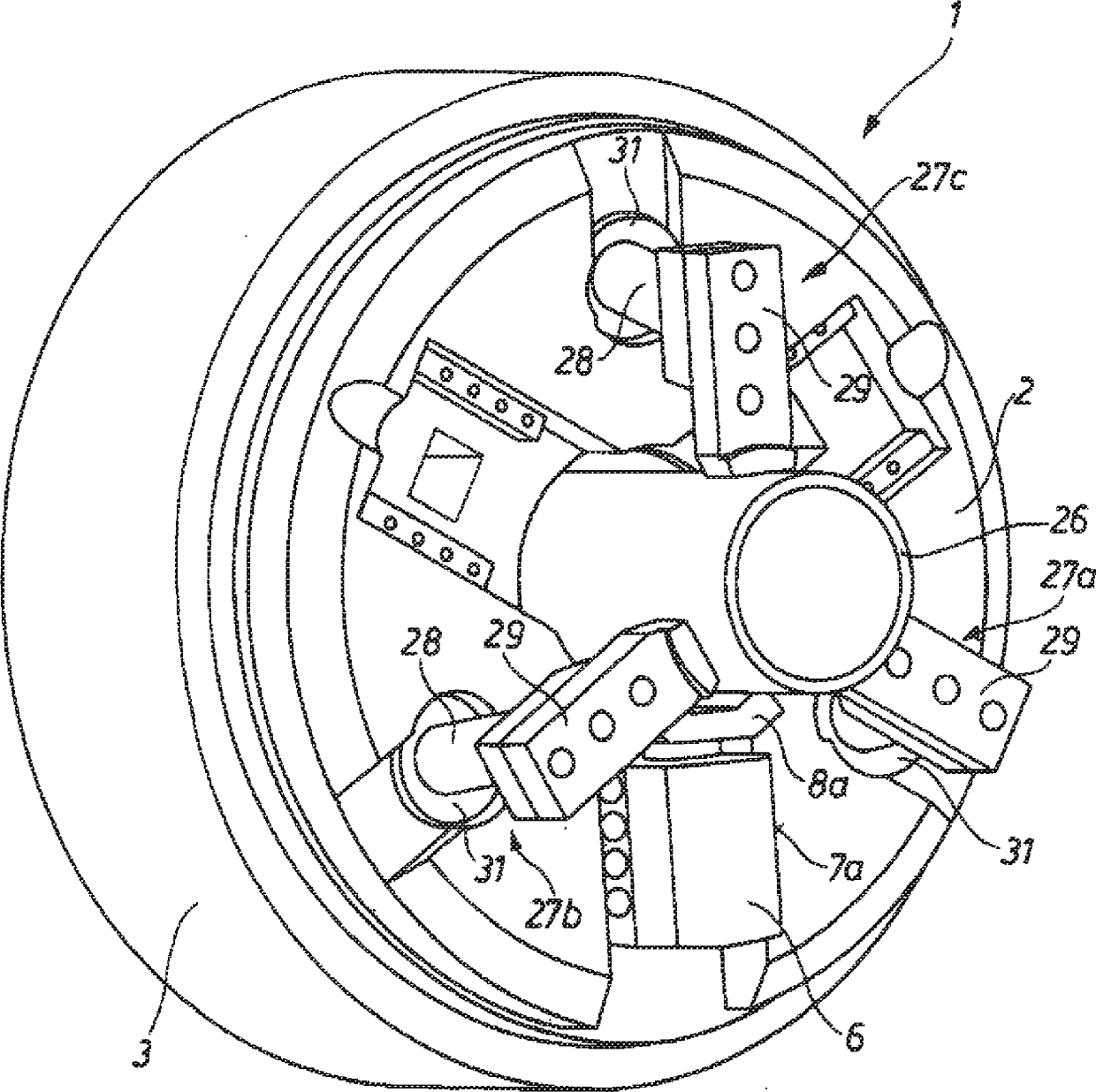
[0022] Machine tools for cutting threads or threaded joints at pipe ends figure 1 The chuck 1 shown in is composed of a top plate 2 and a rearwardly coupled housing ring 3 . In order to accommodate the tube 26 to be processed (see figure 2 ), the chuck 1 has a central through hole 4 whose center 5 coincides with the axis of rotation of the tube rotating in the chuck. Arranged on the end face of the top plate 2 evenly distributed over the circumference are three clamping slides with clamping jaws 8 a, b, c, which are covered by a cover 6 and can be adjusted radially to the center or axis of rotation 5 7a,b,c which center the tube on the center or axis of rotation 5 (see Figure 6 ) to clamp.

[0023] In order to adjust the clamping slides 7a, b, c with the clamps 8a, b, c in the direction of the center or the axis of rotation 5 of the chuck 1, each clamping slide 7a, b, c is tangential to The axis of rotation 5 is associated with transverse slides 9 a, b, c integrated in t...


PUM


Abstract

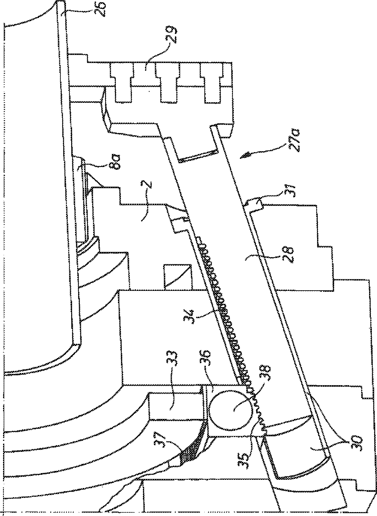
The invention relates to a chuck (1) for a machine tool for machining a tubular workpiece (26) which rotates about a rotational axis that coincides with the centre of the chuck, comprising at least two chucking slides (7a, b, c) that are designed to be positionable radially with respect to the rotational axis in order to release and chuck the workpiece, are arranged on the end side of and in a manner distributed uniformly around the circumference of a chuck head plate, and bear chucking jaws (8a, b, c). Such a chuck is intended to be created with improved operating characteristics and extension to all chucking functions. To this end, for the external central chucking of a tube (26), there are provided centring slides (27a, b, c) which can be disengaged from the chuck head plate with a forward inclination towards the end of the tube to be machined and centre the tube by means of chucking claws (29) which are arranged at the front, free end of centring slide rods (28), said centring slides (27a, b, c) engaging via a toothed rod section (34) into a toothing (35) of a drive means assigned to each centring slide, and meshing for their part, on a toothing side (37) parallel to the side with the toothing, with a central toothed wheel (33) arranged concentrically with the rotational axis, wherein the central toothed wheel (33) synchronizes the movements of all the centring slides (27a, b, c).

Description

technical field [0001] The invention relates to a chuck for a machine tool for machining tubular workpieces that rotate about an axis of rotation that coincides with the center of the chuck, comprising an adjustable radially relative to the axis of rotation for loosening and clamping the workpiece At least two clamping slides (Spannschieber) of a ground-shaped design, which are arranged distributed on the end side and uniformly over the circumference of the chuck top plate (Kopfplatte), carry the clamping jaws (Spannbacke). Background technique [0002] A machine tool for machining tube ends of tubular workpieces rotating about an axis of rotation, in particular for cutting threaded couplings, is known from DE 10 2009 053 679 A1. Pipe threads are usually produced on clamped tubular workpieces or pipe ends in a single pass of a tool, often arranged in a turret head, wherein the movement of the tool is controlled digitally. For clamping the tube, the machine tool has a front ...

Claims


Application Information

Patent Timeline
Patent Type & Authority Applications(China)
IPC IPC(8): B23B31/16B23B31/12
CPCB23B2231/00B23B31/16B23B2270/12B23B31/1223B23B31/16066B23B2231/22Y10T279/17666Y10T279/1946Y10T279/1921Y10T279/1913Y10T279/1926
Inventor K-J.埃泽R.德里克斯
Owner SMS MEER
Learn More