Panel joining structure and panel joining method

A technology for joining structures and panels, applied in the direction of connection between superstructure sub-assemblies, superstructure, superstructure sub-assemblies, etc., can solve another scraping, adhesive dripping in adhesive joints It can prevent dripping or scraping, ensure the bonding quality, and improve the bonding strength.

Active Publication Date: 2014-09-03
TOYOTA JIDOSHA KK
View PDF15 Cites 10 Cited by
  • Summary
  • Abstract
  • Description
  • Claims
  • Application Information

AI Technical Summary

Problems solved by technology

[0010] However, in this structure, for example, when bonding the joining part and the joined part, in the state where one of the joining part and the joined part is arranged in the vertical direction, if one of the joining part and the joined part If the adhesive is applied on one side, the adhesive may drip due to gravity
[0011] In addition, even if the state where the adhesive is applied to one of the joint part and the joined part can be maintained, when the other of the joint part and the joined part moves in the vertical direction and approaches the joint part and the joined part Adhesive may also be scraped off by one of the joints and by the other of the joints

Method used


Image

  • Panel joining structure and panel joining method
  • Panel joining structure and panel joining method
  • Panel joining structure and panel joining method

Examples


no. 1 approach

[0037] First, a first embodiment of the present invention will be described.

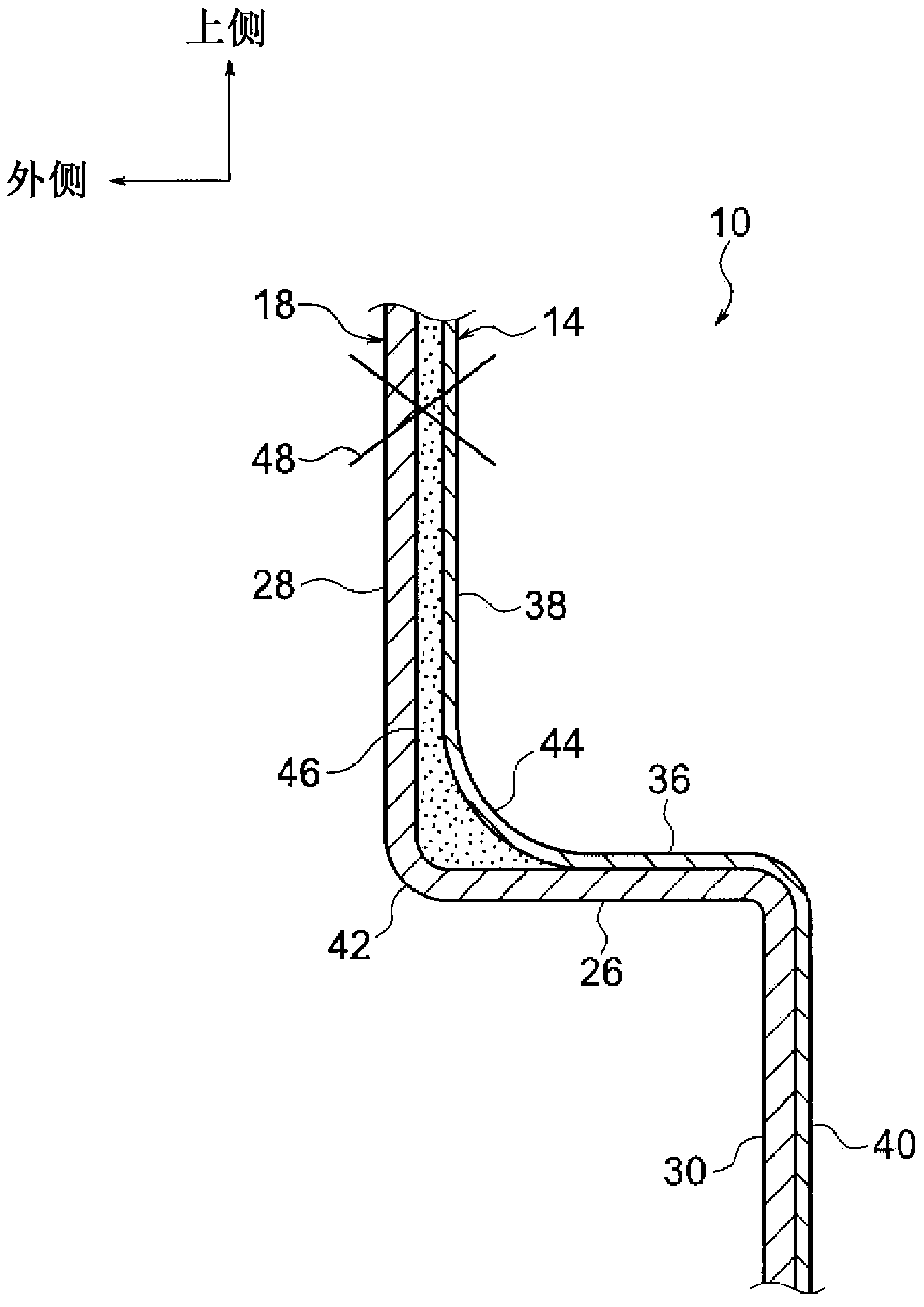
[0038] In addition, arrow UP and arrow OUT shown in each figure indicate the upper side in the vehicle vertical direction and the outer side in the vehicle width direction, respectively. The vehicle up-down direction is an example of a vertical direction in the present invention, and the vehicle width direction is an example of a direction intersecting the vertical direction in the present invention.

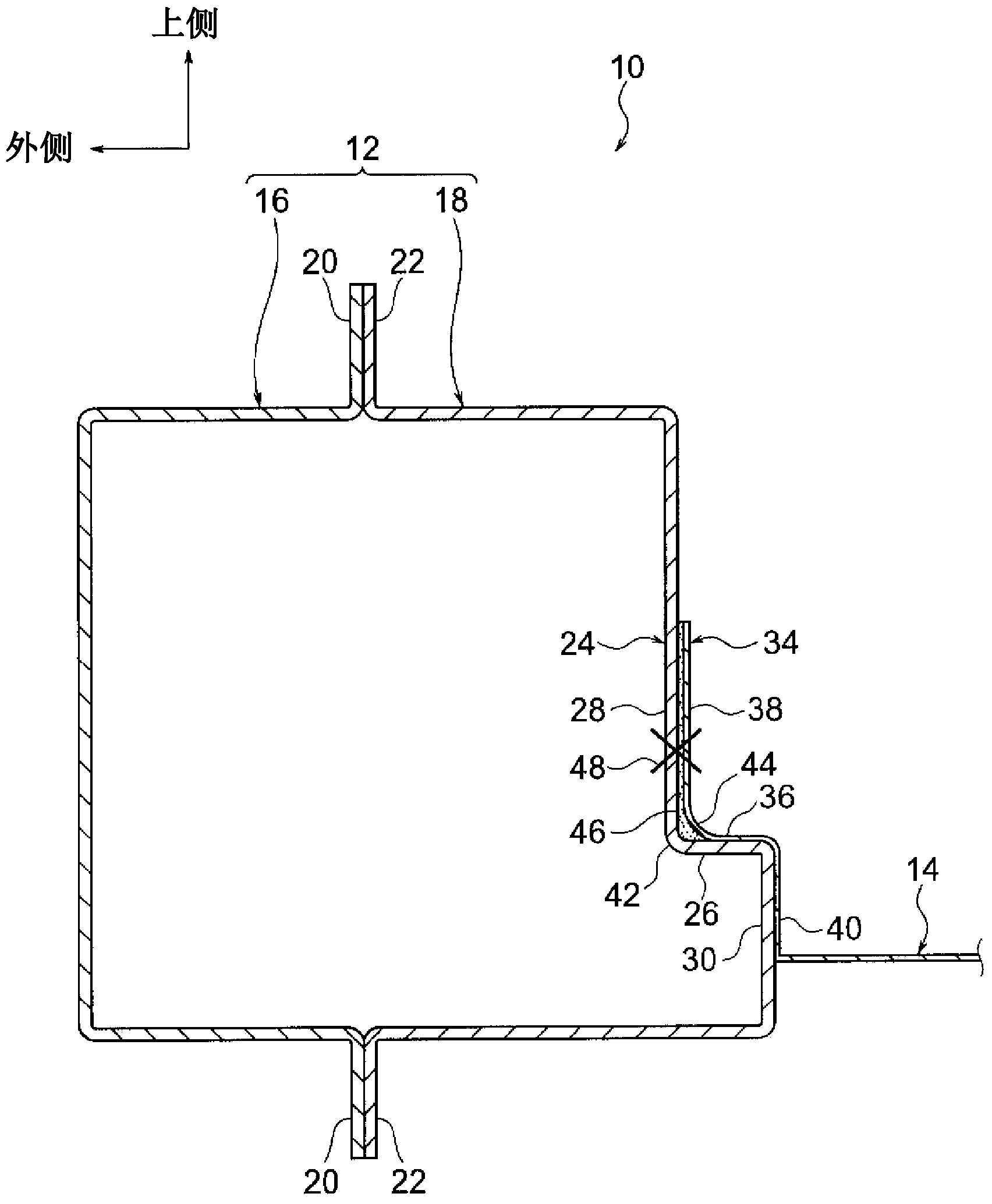
[0039] figure 1 The illustrated panel joint structure 10 according to the first embodiment of the present invention is applied to, for example, a vehicle body of a car or the like, and has a rocker 12 and a floor panel 14 . The rocker 12 is provided on the side of the floor of the vehicle compartment and extends in the front-rear direction of the vehicle. The rocker 12 has a closed cross-sectional shape in a vehicle front view, and has a rocker outer panel 16 and a rocker inner panel 18 which are di...

no. 2 approach

[0064] Hereinafter, a second embodiment of the present invention will be described.

[0065] With respect to the above-mentioned panel joining structure 10 of the first embodiment of the present invention (see figure 2 ), Figure 5 The panel joining structure 60 according to the second embodiment of the present invention shown has a structural change as follows.

[0066] That is, in this panel joint structure 60 , the stepped portion 26 extends in a direction (arrow A direction) inclined with respect to the vehicle width direction as an example of a direction intersecting the vehicle vertical direction. That is, the stepped portion 26 is inclined with respect to the vehicle width direction so as to be directed toward the lower side of the vehicle as it goes inward in the vehicle width direction. In addition, the facing portion 36 also extends in a direction inclined with respect to the vehicle width direction similarly to the above-mentioned step portion 26 .

[0067] In a...


PUM


Abstract

The problem addressed by the present invention is inhibiting the dripping down or scraping off of adhesive when a part to be joined and a part to be joined with are bonded. This panel joining structure (10) is provided with a first panel (18) having a step part (26) extending in a direction that crosses a vertical direction and a joining part (28) extending upward in the vertical direction from one end part of the step part (26) in that crossing direction, and a second panel (14) having a facing part (36) that extends in that crossing direction and also is made to overlap the step part (26) on the upward vertical direction side, a part (38) to be joined that extends in the upward vertical direction from one end part of the facing part (36) in that crossing direction and is joined to the joining part (28) by adhesion and welding, and a downward part (40); that extends downward in the vertical direction from the other end of the facing part (36) in that crossing direction.

Description

technical field [0001] The invention relates to a panel joint structure and a panel joint method. Background technique [0002] Conventionally, there is known a vehicle body joining structure in which joining portions and joined portions respectively formed on inner panels and outer panels constituting reinforcements are bonded and welded (for example, refer to Patent Document 1). [0003] prior art literature [0004] patent documents [0005] Patent Document 1: Japanese Patent Laid-Open No. 2011-98619 [0006] Patent Document 2: Japanese Unexamined Patent Publication No. 2007-22262 [0007] Patent Document 3: Japanese Patent Laid-Open No. 2010-242943 [0008] Patent Document 4: Japanese Patent Laid-Open No. 2009-214841 [0009] The problem to be solved by the invention [0010] However, in this structure, for example, when bonding the joining part and the joined part, in the state where one of the joining part and the joined part is arranged in the vertical direction...

Claims


Application Information

Patent Timeline
Patent Type & Authority Applications(China)
IPC IPC(8): B62D25/20
CPCF16B11/006B23K31/02B62D25/2036B62D27/026B23K2201/006B23K2101/006
Inventor 五嵨俊弘
Owner TOYOTA JIDOSHA KK
Why Eureka
Try Eureka