
Patsnap Eureka
For R&D, Patsnap Eureka makes reading and utilizing patents & technical documents easy.
Patsnap Eureka AIR
Designed for self-driven R&D workflows. Generate viable solutions, solve complex R&D challenges, empower your innovation with AI.

Patsnap Eureka Materials
Designed for material experts only. Revolutionize your material R&D, from search, analyze, to developing new materials.

TechResearch
Generate reliable direction feasibility study reports for your R&D in just a few steps.

TechSeek
Discover and master advanced knowledge NOW. Basics, ideas, possibilities, all at once.

TechMind
As an expert in R&D Theories, TechMind can generates customized viable solutions instantly.

TechRisk
Analyze your overall solution with one click, know your potential R&D risks in advance.

TechMonitor
Get weekly tech updates, stay abreast of the latest tech innovations and key insights.
Exhaust gas treatment device
A waste gas treatment device and technology for waste gas, which are applied in the treatment of combustion products, combustion methods, lighting and heating equipment, etc., can solve problems such as pressure loss increase, performance degradation, popcorn-like ash mixing, etc., and achieve proper trapping and damage. inhibiting effect
- Summary
- Abstract
- Description
- Claims
- Application Information
AI Technical Summary
Problems solved by technology
Method used
Image

Examples
Embodiment 1
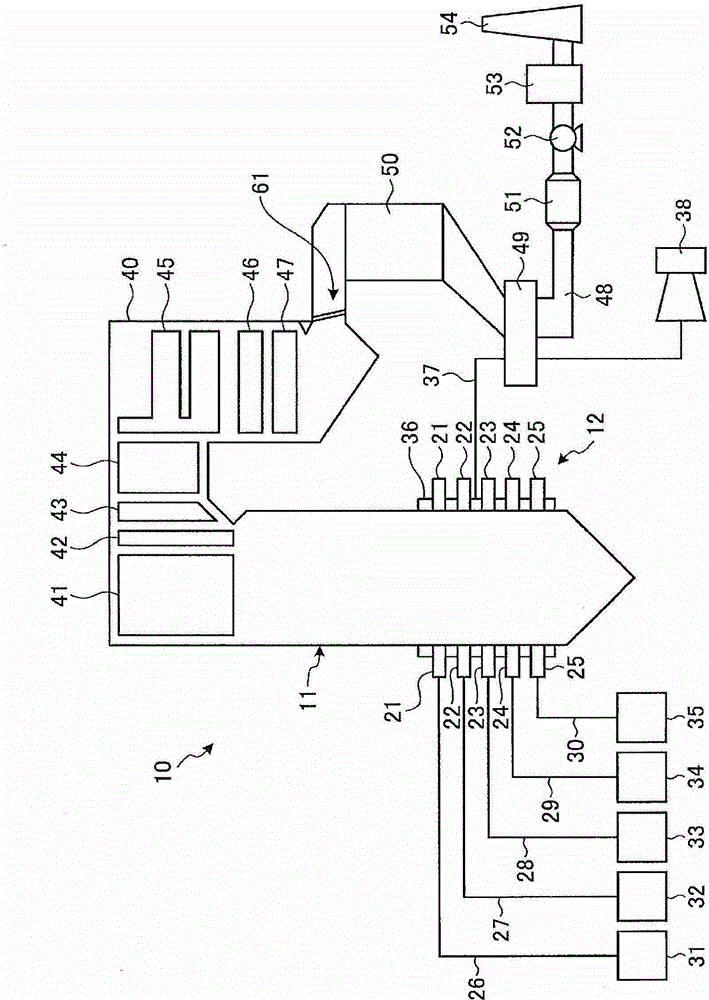
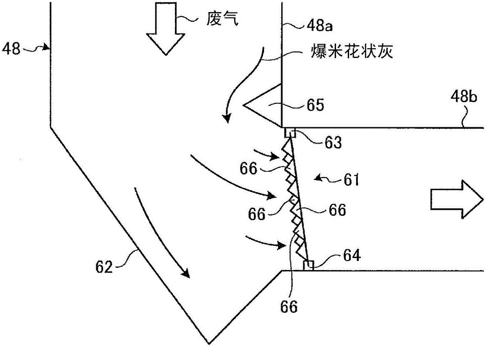
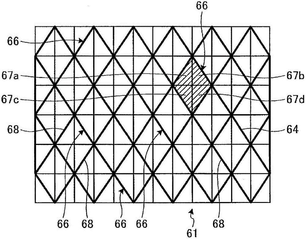
[0039] figure 1 It is a schematic structural diagram showing a pulverized coal-fired boiler to which the exhaust gas treatment device of Embodiment 1 of the present invention is applied, figure 2 is a schematic side view showing the exhaust gas treatment device of Example 1, image 3 It is a front view of the popcorn-shaped ash collection part in the exhaust gas treatment device of Example 1, Figure 4 It is a plan view of the popcorn-shaped ash collecting part of Example 1, Figure 5 It is a side view of the popcorn-shaped ash collection part of Example 1.
[0040] The pulverized coal boiler to which the exhaust gas treatment device of Example 1 is applied is a boiler that uses pulverized coal as a solid fuel, burns the pulverized coal through a burner, and recovers the heat energy generated by the combustion .
[0041] In this Example 1, as figure 1 As shown, the pulverized coal fired boiler 10 is a traditional boiler with a furnace 11 and a combustion device 12 . The...
Embodiment 2
[0073] Figure 6 It is a plan view of the popcorn-shaped ash collection part in the exhaust gas treatment device of Example 2 of the present invention. Figure 7 It is a side view of the popcorn-shaped ash collection part of Example 2.
[0074] In Example 2, the basic structure of the exhaust gas treatment device is the same as that of Example 1, and only the structure of the popcorn-shaped ash collecting part is different. Such as Figure 6 and Figure 7 As shown, the plurality of protrusions 72a, 72b of the popcorn-shaped ash collecting portion 71 protrude forward in the exhaust gas flow direction, and the plurality of protrusions 72a, 72b are arranged in parallel along two intersecting directions. All of the plurality of protrusions 72a disposed at the central portion of the exhaust pipe have the same shape. In addition, all the plurality of protrusions 72b with respect to the flow direction of the exhaust gas have the same shape. Moreover, since one protrusion part 72...
Embodiment 3
[0083] Figure 8 It is a front view of the popcorn-shaped ash collecting part in the exhaust gas treatment device of Example 3 of the present invention, Figure 9 It is a plan view of the popcorn-shaped ash collecting part of Example 3, Figure 10 It is a side view of the popcorn-shaped ash collection part of Example 3.
[0084] In Example 3, the basic structure of the exhaust gas treatment device is the same as that of Example 1, and only the structure of the popcorn-shaped ash collecting part is different. Such as Figure 8 to Figure 10 As shown, the plurality of protrusions 82 and 83 of the popcorn-shaped ash collection part 81 protrude forward in the exhaust gas flow direction, and the plurality of protrusions 82 and 83 are arranged in parallel along two intersecting directions.
[0085] Although all of the plurality of protrusions 82 and 83 have the same shape, the protrusion 82 and the protrusion 83 are formed in a line-symmetrical shape. That is, since the protrusio...
PUM
 Abstract
Description
Claims
Application Information
 - R&D Engineer
- R&D Manager
- IP Professional
- Industry Leading Data Capabilities
- Powerful AI technology
- Patent DNA Extraction
Browse by: Latest US Patents, China's latest patents, Technical Efficacy Thesaurus, Application Domain, Technology Topic, Popular Technical Reports.
© 2024 PatSnap. All rights reserved.Legal|Privacy policy|Modern Slavery Act Transparency Statement|Sitemap|About US| Contact US: help@patsnap.com