Cutting assembly of stapler

A technology for staplers and components, which is applied in the fields of cutting components of circular staplers and curved staplers, linear cutting staplers, and stapler cutting components. Problems, achieve the effect of accelerating tissue healing, shortening operation time, and shortening time

Inactive Publication Date: 2014-09-10
SHANDONG WEIRUI SURGICAL MEDICAL PROD
View PDF4 Cites 8 Cited by
  • Summary
  • Abstract
  • Description
  • Claims
  • Application Information

AI Technical Summary

Problems solved by technology

The currently used cutting assembly with multiple rows of staples arranged on the surface of the staple cartridge has the same height of staples on the inside and outside, which is not conducive to hemostasis and tissue blood supply.
In addition, there is no drop on the surface of the staple cartridge, the pressing force on the tissue is not dispersed, the tissue fluid is not easy to drain, and it takes a long time for the tissue to be compressed to a certain thickness, which is time-consuming and laborious to use

Method used


Image

  • Cutting assembly of stapler
  • Cutting assembly of stapler
  • Cutting assembly of stapler

Examples


Embodiment Construction

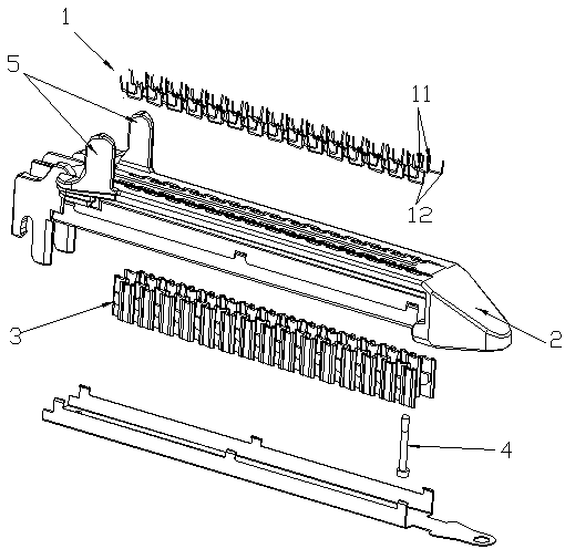
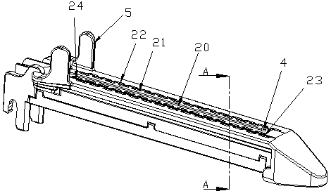
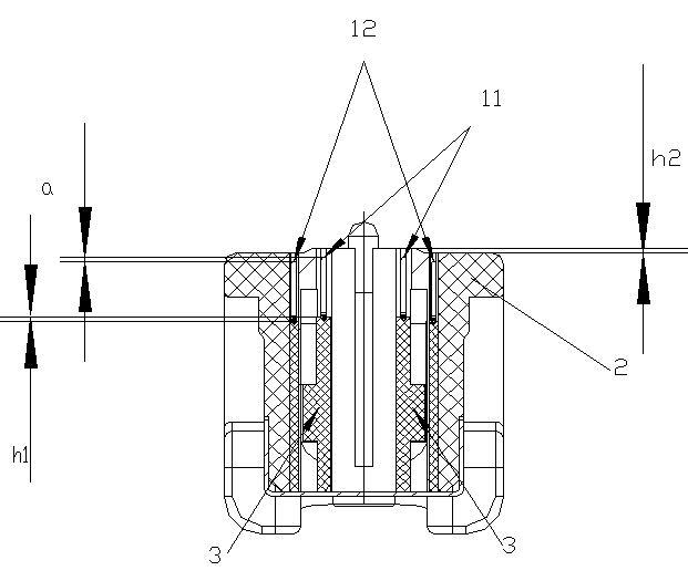
[0014] The stapler cutting assembly includes a staple cartridge 2, a staple pusher 3 installed in the staple cartridge 2 and a staple 1 pushed by the teeth of the staple pusher 3. The surface of the staple cartridge is provided with a pusher groove 20, and the surface of the staple cartridge is distributed For more than two rows of cartridge holes, the cartridge holes arranged close to the push knife groove 20 are the inner staple cartridge holes 21, and the staple cartridge holes arranged away from the push knife groove 20 are the outer staple cartridge holes 22. The staple 1 and the staple cartridge The holes 21, 22 are correspondingly distributed. As shown in the figure, the teeth for pushing the outer row of staples 12 are the outer row of teeth 32, and the teeth for pushing the inner row of staples 11 are the inner row of teeth 31, and the height of the inner row of teeth 31 is higher than that of the outer row. The tooth pieces 32, the height difference between the inner...


PUM


Abstract

The invention discloses a cutting assembly of a stapler, and belongs to the field of medical instruments. Staple molding heights of suturing staples of the cutting assembly are inconsistent. By using the height difference of staple pushing grain tooth pieces, under the condition of the consistent heights of the suturing staples, the molding heights are inconsistent, and the outer molded staples are higher than the inner molded staples. The inner molded staples are low to be beneficial to stop bleeding, the outer molded staples are high to be beneficial to the blood supply for tissues to cutting edges, and the healing of the tissues is fast. A staple cartridge surface is designed into a ladder shape, the middle position is higher than the positions of the two sides, so that the squeezing force of the tissues is dispersed, the stress of the middle surface is greater to be beneficial to spread tissue fluid to the two sides, the time for compressing the tissues to the specified height is effectively shortened, and the operation time is shortened. A tissue stop stand column is used for limiting tissue pull-in positions, and interacts with tissue positioning staples to ensure that the length of staple lines always exceeds that of clamping tissues, complete suturing of the tissues is ensured, and no exposure point is generated.

Description

technical field [0001] The invention belongs to the field of medical instruments, and in particular relates to a stapler cutting assembly, in particular to a cutting assembly suitable for linear cutting staplers, circular staplers and arc-shaped staplers. Background technique [0002] Stapler is a commonly used clinical instrument, the main purpose is to perform tissue separation, resection and anastomosis. Whether it is a linear cutting stapler or a circular cutting stapler, the cutting component is an important part. During use, it is necessary to place the tissue between the anvil and the staple cartridge on the head of the instrument, then squeeze the handle, and the staple cartridge will move closer to the anvil. The staples in the staple cartridge are pushed from the staple cartridge holes into the nail grooves and extruded into a B-shape. The currently used cutting assembly of multiple rows of staples arranged on the surface of the staple cartridge has the same heig...

Claims


Application Information

Patent Timeline
Patent Type & Authority Applications(China)
IPC IPC(8): A61B17/072A61B17/3209
CPCA61B17/07207A61B17/1155A61B17/3209A61B2017/07285
Inventor 邹锋马波姚大强邵威韩爱荣
Owner SHANDONG WEIRUI SURGICAL MEDICAL PROD
Why Eureka
Try Eureka