
Cooling water circulation device for condensation point instrument

A technology of cooling water circulation and condensation point instrument, which is applied in heating or cooling equipment, chemical instruments and methods, laboratory appliances, etc., can solve the problems of artificially collecting water sources, occupying a large space, and manpower handling, etc., so as to improve the utilization rate of water sources , low cost and easy implementation

Inactive Publication Date: 2014-09-10
STATE GRID CORP OF CHINA +1
View PDF0 Cites 2 Cited by
  • Summary
  • Abstract
  • Description
  • Claims
  • Application Information

AI Technical Summary

Problems solved by technology

[0004] Solution 1: Collect cooling water with the help of plastic buckets and other containers; Disadvantages: 1. It needs to be done artificially when collecting water; 2. It needs to buy a sufficient number of buckets, and it takes up a lot of space; 3. It takes water resources to make other uses Manual handling
Solution 2: By reducing the water output of tap water, disadvantages: 1. The operation is simple and easy to realize; the overall water saving is very limited; 2. The water pressure required by the condensation point meter is often not reached

Method used


Image

  • Cooling water circulation device for condensation point instrument
  • Cooling water circulation device for condensation point instrument
  • Cooling water circulation device for condensation point instrument

Examples

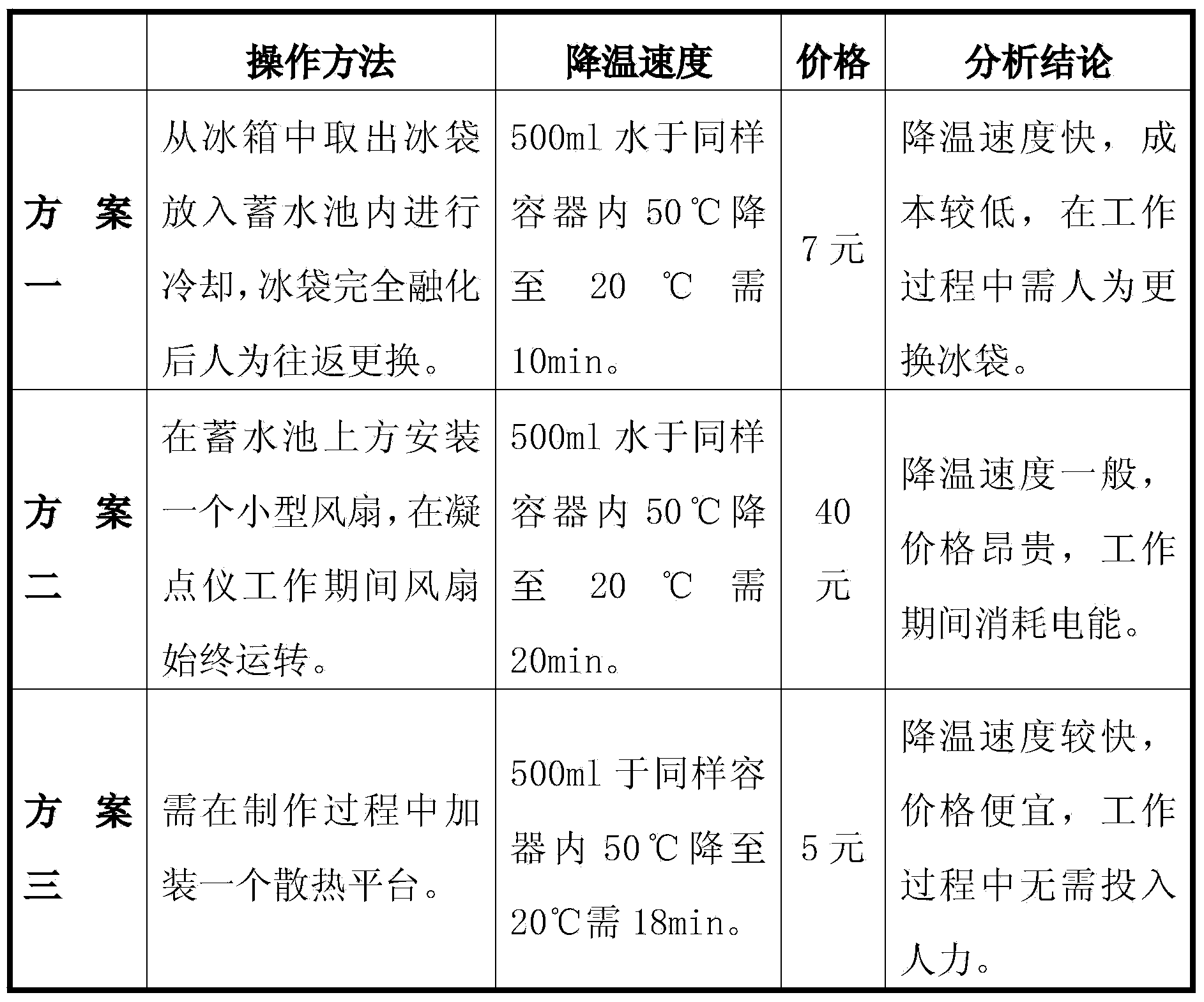

Embodiment Construction

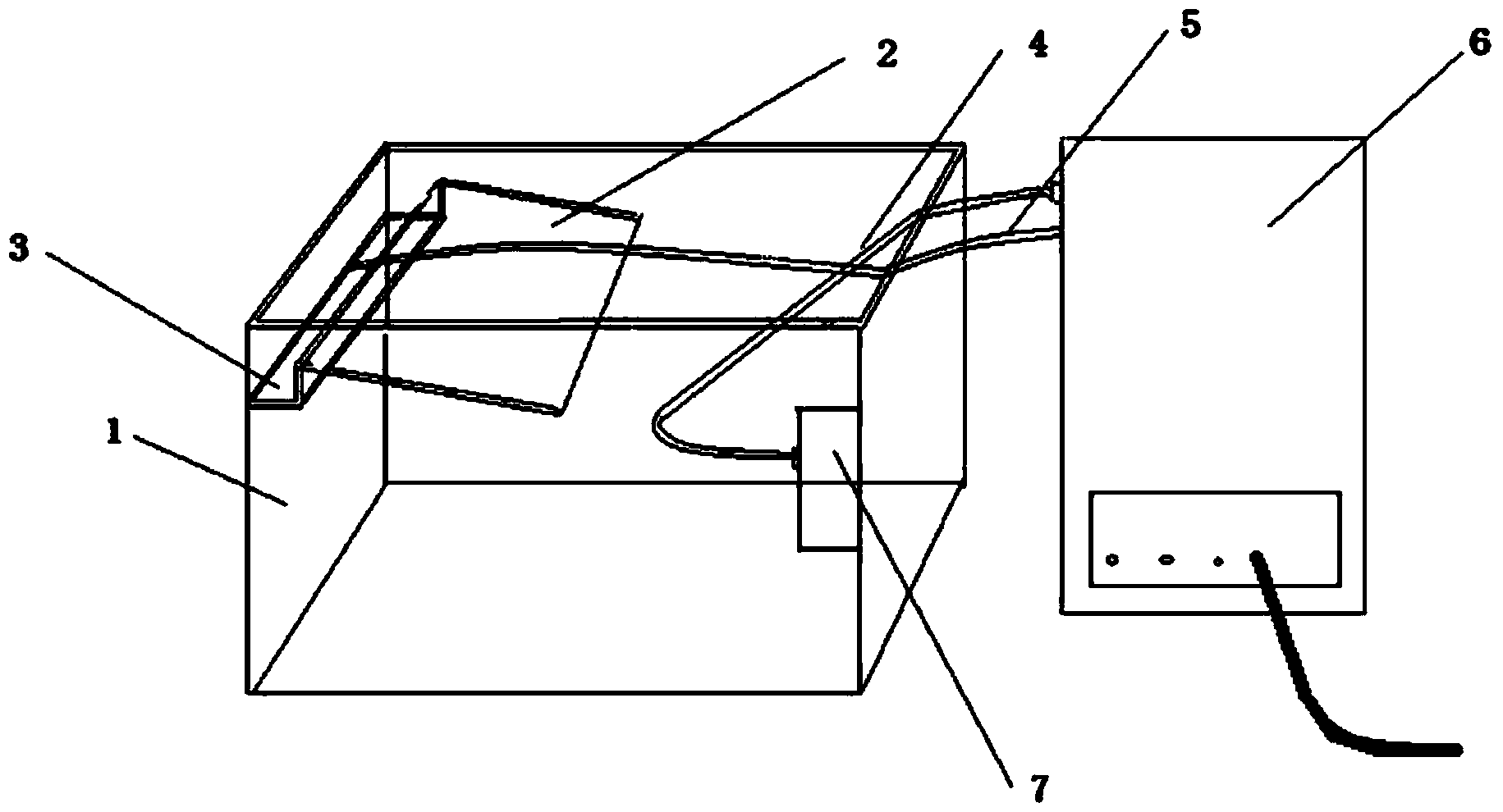
[0020] Such as figure 1 Shown: a cooling water circulation device designed for a freezing point instrument, including a reservoir 1, an auxiliary heat dissipation surface 2, a water storage groove 3, a centrifugal water pump 7, and a freezing point instrument 6; the auxiliary heat dissipation surface 2 is placed obliquely Inside the water storage tank 1, the upper edge of the water storage groove 3 is connected with the auxiliary cooling surface 2, and the lower edge of the water storage groove 3 is connected with the water storage tank 3; the centrifugal water pump 7 is connected with the condensation Point instrument 6 is connected by water inlet pipe 4; Described water inlet pipe 4 one ends connect the water outlet of centrifugal water pump 7, the other end connects the water inlet of coagulation point instrument 6, described outlet pipe 5 one ends and the outlet of coagulation point instrument 6 The water ports are connected, and the other end is fixed at the water storage...


PUM


Abstract

The invention relates to a cooling water circulation device for a condensation point instrument, and belongs to the technical field of power supply equipment. The cooling water circulation device comprises a water reservoir, an auxiliary heat radiation surface, a water storage groove, a centrifugal water pump and the condensation point instrument, wherein the auxiliary heat radiation surface is arranged inside the water reservoir in an inclined manner; the upper edge of the water storage groove is connected with the auxiliary heat radiation surface; the lower edge of the water storage groove is connected with the water reservoir; the centrifugal water pump is connected with the condensation point instrument through a water inlet tube; one end of the water inlet tube is connected with a water outlet of the centrifugal water pump; the other end of the water inlet tube is connected with a water outlet of the condensation point instrument; one end of a water outlet tube is connected with the water outlet of the condensation point instrument; the other end of the water outlet tube is fixed at the water storage groove. Compared with the prior art, due to adoption of the centrifugal water pump, the cooling water circulation device can solve the technical problems that cooling water is circulated and repeatedly used, the utilization rate of water resources is increased and the water resources are greatly saved; due to additional arrangement of the auxiliary heat radiation surface of a glass steel body, a function of auxiliary heat radiation is achieved; moreover, the energy conservation, the environment friendliness and the low cost are achieved indeed, the construction is convenient, and the popularization and the application are facilitated.

Description

technical field [0001] The invention belongs to the technical field of power supply equipment, and in particular relates to a cooling water circulation device for a freezing point instrument used by a power supply enterprise. Background technique [0002] When conducting routine test analysis in the chemical laboratory, the cooling method of the condensation point instrument for the condensation point test adopts natural water cooling, and the tap water flows into the instrument and then flows into the sewer along the pipeline after cooling. [0003] According to statistics, it takes 90 minutes to conduct a freezing point test, and the water consumption for 1 minute is 4.5kg, and the total water consumption is 0.4 tons. The freezing point test is a routine analysis test that must be done for insulating oil acceptance, and the test frequency is very high. Especially during the spring and autumn inspection period, the condensation point instrument works all day, and the water ...

Claims


Application Information

Patent Timeline
Patent Type & Authority Applications(China)
IPC IPC(8): B01L7/00
Inventor 王允贾晨牛小威李红卫刘佳佳柴金慧
Owner STATE GRID CORP OF CHINA
Learn More