Pistol-drill clamping mechanism suitable for milling of circular groove

A clamping mechanism, pistol drill technology, applied in portable drilling rigs, manufacturing tools, portable mobile devices, etc., can solve the problems of inconvenient connection of other equipment or tooling, affecting the processing accuracy of materials, etc., to achieve simple structure, high processing accuracy, good quality The effect of milling accuracy

Inactive Publication Date: 2014-09-10
API ZC PRECISION INSTUMENT CO LTD
View PDF5 Cites 10 Cited by
  • Summary
  • Abstract
  • Description
  • Claims
  • Application Information

AI Technical Summary

Problems solved by technology

[0004] In order to solve the above-mentioned problems in the prior art that the vibration generated during the working process of the pistol drill affects the processing accuracy of materials and is inconvenient to connect with other equipment or tooling, the present invention provides a pistol drill clamping mechanism suitable for annular groove milling

Method used


Image

  • Pistol-drill clamping mechanism suitable for milling of circular groove

Examples


Embodiment 1

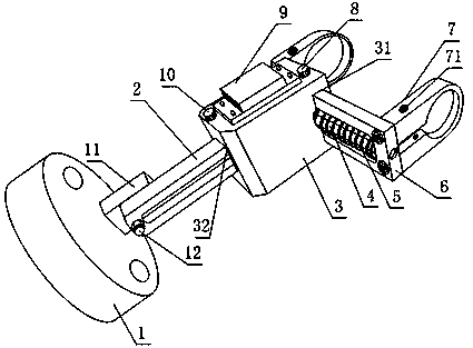
[0022] Such as figure 1 , a pistol drill clamping mechanism suitable for annular groove milling provided by the present invention, including at least two hoop-shaped hoop parts 7, a first sliding seat 2, a second sliding seat 6, and a slider 3 And the base 1, the base 1 is also provided with a hinged rod 11, the hoop parts 7 are parallel to each other and are respectively fixed on one end of the second sliding seat 6, both on the first sliding seat 2 and the second sliding seat 6 A slide rail is provided, and the slide block 3 is provided with a first slide groove 31 and a second slide groove 32 respectively matched with the slide rails, and the two slide rails are partially located in the first slide groove 31 or the second slide groove 32 respectively. , and the first chute 31 and the second chute 32 are perpendicular to each other, the slider 3 can slide along the slide rail, the hinge rod 11 or the first sliding seat 2 is also provided with a hinge nail 12, the hinge rod 1...

Embodiment 2

[0025] This embodiment is further limited on the basis of embodiment 1: as figure 1 , the hoop portion 7 is a U-shaped structure provided with an annular through hole, and the hoop portion 7 is also provided with a tightening bolt hole 71 for adjusting the size of the annular through hole, the hoop portion 7 Be connected with the second sliding seat 6 by bolts.

[0026] The hoop portion 7 of the above structural form is simple in structure, and the annular through hole is used to match the shell of the pistol drill, and the hoop bolt hole 71 is used to install the locking bolt. After the pistol drill is put into the two hoop portions 7, The size of the annular through hole is reduced by the locking bolt, so that the present invention is suitable for the installation of pistol drills within a certain size range; at the same time, the hoop part 7 and the second sliding seat 6 are in a bolted structural form, which is convenient for replacing different The size of the hoop porti...

Embodiment 3

[0028] The present embodiment is further limited on the basis of embodiment 1: as figure 1 , in order to enable the pistol drill to automatically reset on its axis, so as to optimize the processing efficiency of the present invention in the axial direction of the hole, the second sliding seat 6 is block-shaped, and the first chute on the slider 3 31 is a T-shaped slot, and a spring 5 fixedly connected to it at one end is also arranged on the second sliding seat 6 , and the other end of the spring 5 is in contact with the slider 3 .

[0029] In order to make the present invention applicable to the drilling of deep holes, that is, to extend the length of the slide rail 61, in order to make the longer spring 5 not bend in the deformation process in this case, so as to facilitate the stability of the present invention's work, the described The second sliding seat 6 is also provided with a guide rod 4 which is threaded or bolted, the spring 5 is sleeved on the guide rod 4 , and the...


PUM


Abstract

The invention discloses a pistol-drill clamping mechanism suitable for milling of circular grooves. The pistol-drill clamping mechanism comprises at least two hoop-shaped hoop portions, a first sliding base, a second sliding base, a sliding block and a pedestal. The pedestal is further provided with a hinge rod, the hoop portions are parallel and are respectively fixed to one end of the second sliding base, the first sliding base and the second sliding base are respectively provided with a sliding rail, the sliding block is provided with a first sliding groove and a second sliding groove which are matched with the sliding rails respectively, and the first sliding groove is perpendicular to the second sliding groove. The hinge rod or the first sliding base is further provided with a hinge nail, the hinge rod is connected with the first sliding base in a hinged mode through the hinge nail, and the first sliding base can rotate around the axis of the hinge nail. The pistol-drill clamping mechanism is simple in structure, and hole milling is conveniently carried out through a pistol drill; compared with the situation that the pistol drill is held by an operator with hand in the prior art, arcs with the same diameter or arcs with different diameters are milled conveniently, and improvement on machining precision and machining efficiency of the pistol drill is facilitated.

Description

technical field [0001] The invention relates to a processing equipment fixture, in particular to a pistol drill clamping mechanism suitable for ring groove milling. Background technique [0002] At present, the pistol drills commonly used in the market include drill bits, shafts, casings, motors, etc., through one-way or two-way rotation, can be conveniently and flexibly used for drilling, boring or even milling in the production process. In the field of equipment production, the manual tube expander can even be clamped at the drill bit end of the pistol drill, and the mechanical energy of the motor can be used to replace the manual rotation of the operator. [0003] The shell of the pistol drill in the prior art is provided with a gripping part, but the pistol drill vibration caused by the resistance of the material during the working process of the pistol drill affects the accuracy of the pistol drill for material processing, while the shell of the pistol drill in the prio...

Claims


Application Information

Patent Timeline
Patent Type & Authority Applications(China)
IPC IPC(8): B23B45/00B25F5/00
CPCB25H1/0021
Inventor 刘宁李德维罗成
Owner API ZC PRECISION INSTUMENT CO LTD
Why Eureka
Try Eureka