
Cut-off PCB (printed circuit board) separator

A technology of PCB board and board splitting machine, which is applied in the direction of shearing machine equipment, shearing device, metal processing equipment, etc., can solve the problems of expensive consumables, inflexibility, and low efficiency of milling cutters, and achieve air pollution and applicability wide effect

Active Publication Date: 2014-09-10
FORYOU GENERAL ELECTRONICS
View PDF13 Cites 10 Cited by
  • Summary
  • Abstract
  • Description
  • Claims
  • Application Information

AI Technical Summary

Problems solved by technology

In the prior art, there are usually three ways to divide the PCB board, manual division, V-CUT cutting and machine division. Among them, manual division is used, and due to the stress of manual division, solder joints crack It is easy to cause quality problems, and this kind of manual operation is time-consuming and labor-intensive, and the efficiency is very low, which can no longer meet the needs of the production and development of the enterprise; the V-CUT cutting method is adopted, which not only needs to be divided into multiple processes to complete, but also When there are non-linear and multi-angle splitting requirements on the PCB, this processing method cannot be completed; for the latter, the method of splitting the equipment with a milling cutter is complicated to operate, and the milling cutter of the splitting machine When cutting, it is easy to cut the PCB board or damage the circuit on the PCB board and the soldered electronic components, resulting in a high scrap rate and affecting the quality and performance of the product
Moreover, the milling cutter cutting equipment is huge and inflexible in movement, and a special area needs to be set up, which takes up a lot of space in the workshop; a large amount of dust will be generated during the cutting process, which is not environmentally friendly, and it needs to be equipped with a high-power dust collector, which consumes a lot of power (2.2-3.7 kilowatts per hour) ), and the milling cutter consumables are relatively expensive, and the processing cost is high

Method used


Image

  • Cut-off PCB (printed circuit board) separator
  • Cut-off PCB (printed circuit board) separator
  • Cut-off PCB (printed circuit board) separator

Examples


Embodiment

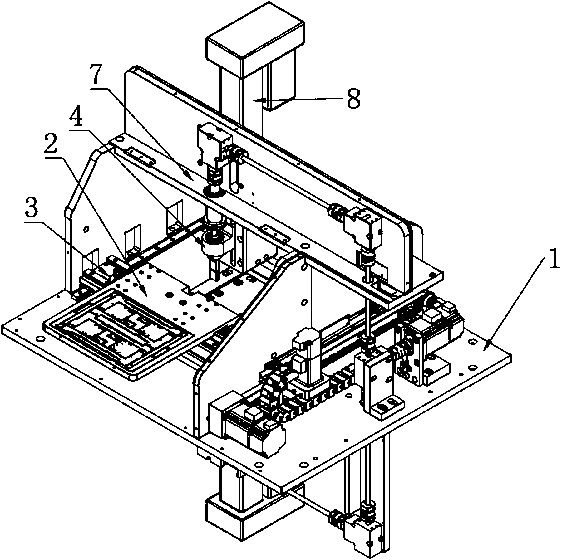
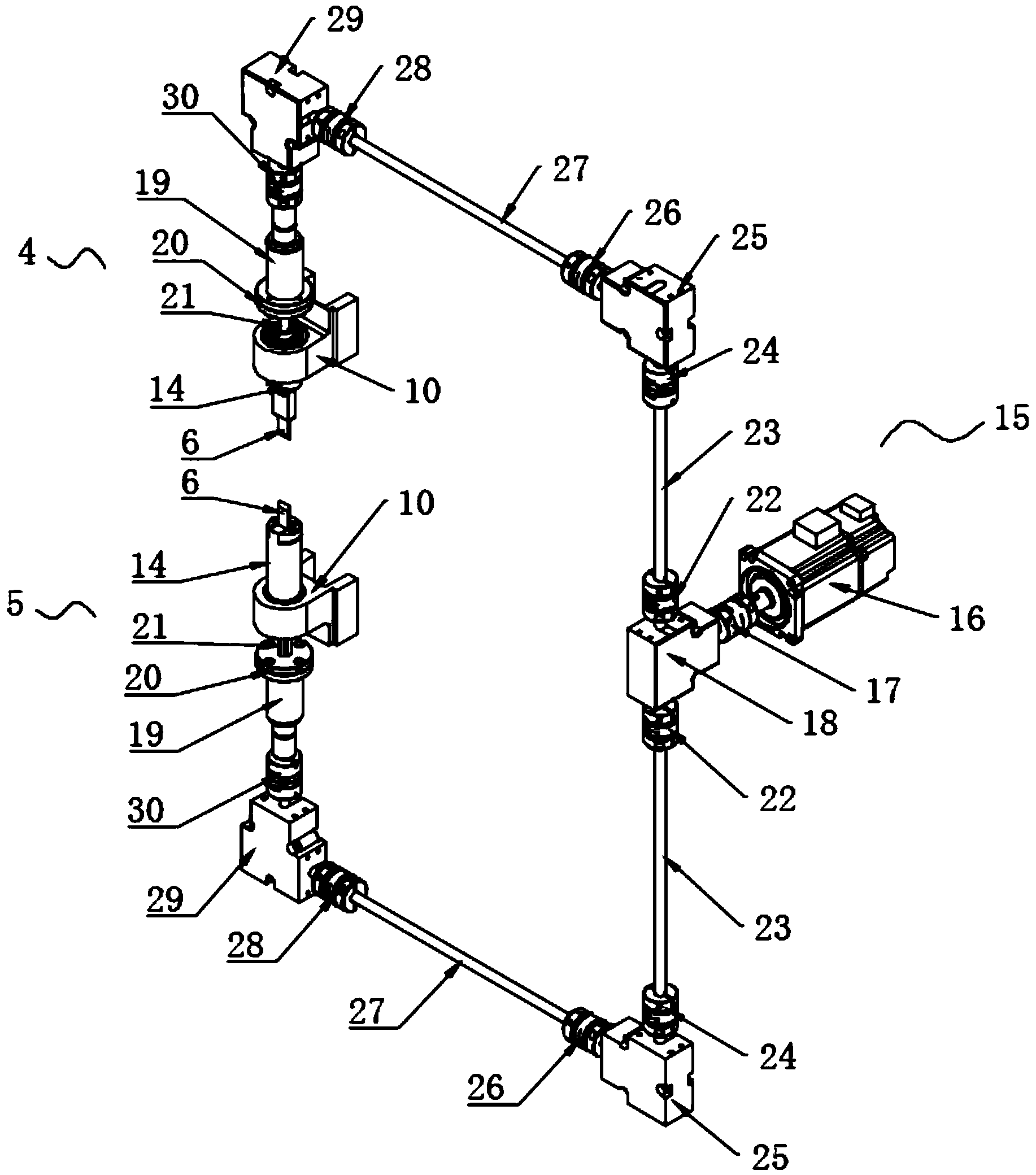
[0024] combine figure 1 and figure 2 As shown, the present embodiment provides a shearing type PCB splitter, including a work platform 1, the work platform 1 is provided with a loading jig 2 for fixing the PCB board and is used to drive the loading jig 2 horizontally on the horizontal working surface. With the X-Y motion platform mechanism 3 that moves longitudinally, the loading jig 2 is installed on the X-Y motion platform mechanism 3, and the upper and lower sides of the loading jig 2 are provided with an upper cutter that cuts the upper and lower sides of the PCB board simultaneously. Knife mechanism 4 and lower cutting knife feeding mechanism 5.

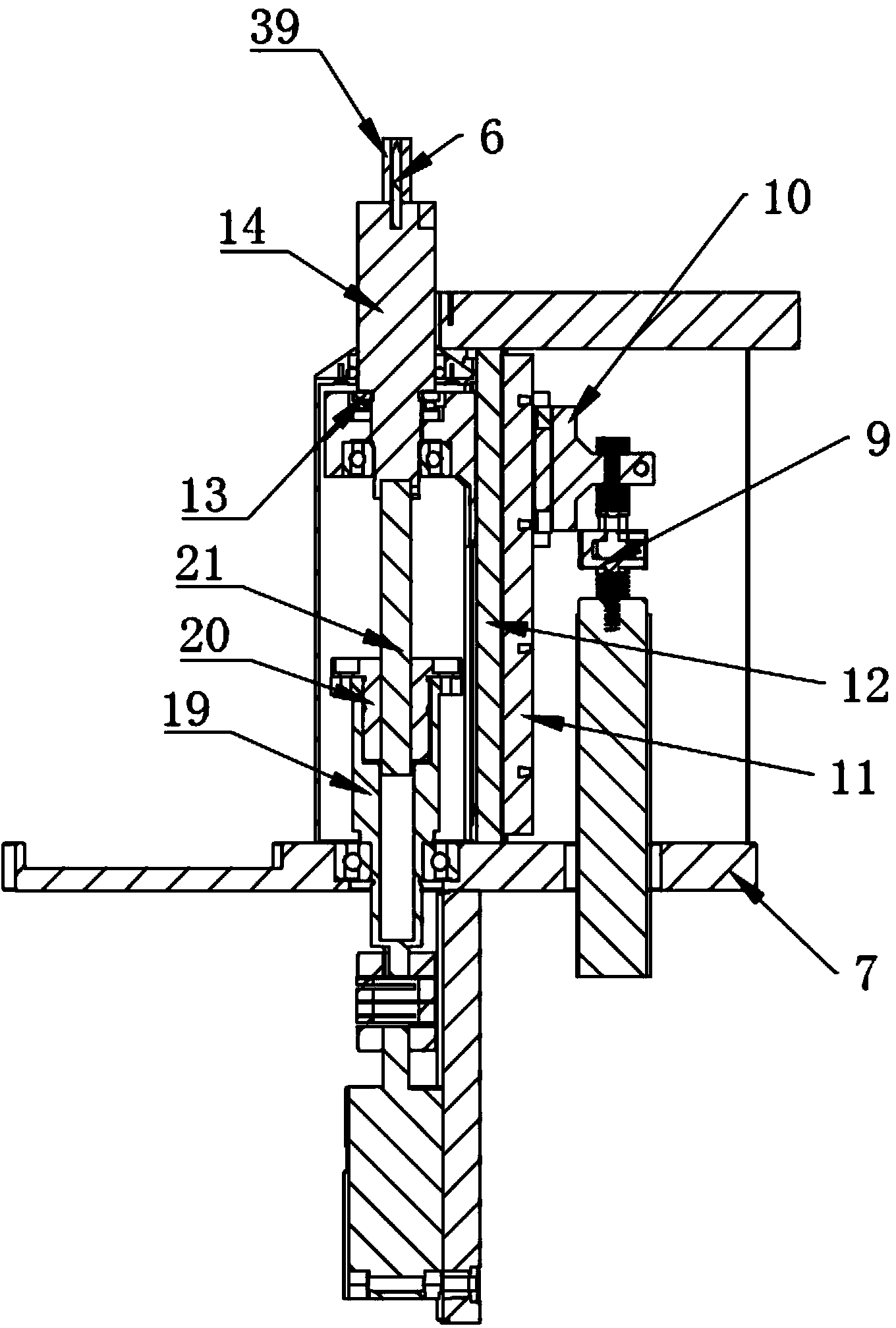
[0025] like figure 2 As shown, the front portion of the upper cutter feed mechanism 4 and the lower cutter feed mechanism 5 is provided with a shear knife 6, and the loading fixture 2 is provided with a processing channel for the shear knife 6 to extend into. The feed mechanism 4 and the lower cutter feed mechanism 5 are sy...


PUM


Abstract

The invention discloses a cut-off PCB (printed circuit board) separator comprising a workbench. A mounting fixture used for fixing a PCB and an X-Y motion platform mechanism driving the mounting fixture to transversely and longitudinally move on a horizontal operating plane are arranged on the workbench. The mounting fixture is mounted on the X-Y motion platform mechanism. An upper cutter feeding mechanism and a lower cutting feeding mechanism for cutting upper and lower surfaces of the PCB respectively at the same time are arranged above and below the mounting fixture. The cut-off PCB separator has the advantages that the upper and lower surfaces of the PCB on the mounting fixture are cut at the same time by the upper cutter feeding mechanism and the lower cutting feeding mechanism, the application of cutting processing prevents quality problems, such as welding spot cracks, caused by stress during separating and also avoids dust, and the air pollution problem caused by cutting processing by a milling cutter is solved, the PCB can flexibly move on the X-Y motion platform mechanism, the requirements for separating under nonlinearity, multi-angle and the like conditions are met, and the cut-off PCB separator is widely applicable.

Description

technical field [0001] The invention relates to the technical field of cutting PCB boards, in particular to a shearing type PCB splitting machine. Background technique [0002] In the printed circuit board (PCB) of electronic products, there is a problem of separating the edge of the PCB board and the excess waste corner material, that is, cutting and dividing the entire PCB board. In the prior art, there are usually three methods of board splitting for PCB boards: manual splitting, V-CUT cutting and machine splitting. Among them, manual splitting is used, and solder joints crack due to stress in manual splitting. It is easy to cause quality problems, and this kind of manual operation is time-consuming and labor-intensive, and the efficiency is very low, which can no longer meet the needs of the production and development of the enterprise; the V-CUT cutting method is adopted, which not only needs to be divided into multiple processes to complete, but also When there are no...

Claims


Application Information

Patent Timeline
IPC IPC(8): B23D15/06
Inventor 黄高兴
Owner FORYOU GENERAL ELECTRONICS
Learn More