Bar adjusting mechanism

An adjustment mechanism and material bar technology, which is applied in the direction of sawing machine devices, metal sawing equipment, metal processing equipment, etc., can solve the problems that the adjustment efficiency and adjustment accuracy cannot be satisfied at the same time, and achieve improved adjustment stability, convenient adjustment, and device settings. simple effect

Active Publication Date: 2014-09-10
三环永磁(北京)科技有限公司
View PDF6 Cites 1 Cited by
  • Summary
  • Abstract
  • Description
  • Claims
  • Application Information

AI Technical Summary

Problems solved by technology

[0006] Therefore, the technical problem to be solved by the present invention is to overcome the technical defect that the bar material adjustment device in the prior art cannot satisfy the adjustment efficien

Method used


Image

  • Bar adjusting mechanism
  • Bar adjusting mechanism
  • Bar adjusting mechanism

Examples


Embodiment 1

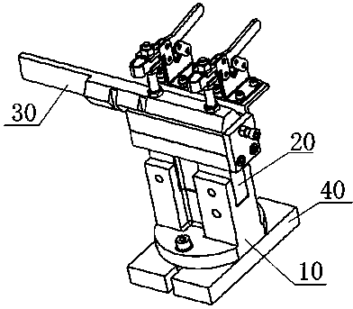
[0056] This embodiment provides a rod adjustment mechanism, such as figure 1 As shown, it includes a second fixing device that fixes the lower bracket 10 on the workbench of the inner circle slicer, and a connecting device that connects the lower bracket 10 and the upper bracket 20, and is used to drive the upper bracket 20 to rotate relative to the lower bracket 10 to adjust The pitch adjusting device of the pitch angle of the material rod 30 installed on the upper bracket 20 is used to prevent the upper bracket 20 from rotating and the non-return positioning device of the upper bracket 20 when the upper bracket 20 stops rotating. The first fixing device that fixes the upper bracket 20 when the rotation of the lower bracket 10 ends, and the third fixing device that fixes the material rod 30 on the upper bracket 20 .

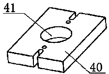
[0057] Such as figure 2 As shown, the above-mentioned second fixing device includes a base 40, two U-shaped grooves arranged on the base 40, through the U-sha...


PUM


Abstract

The invention provides a bar adjusting mechanism which comprises a lower support and an upper support. The lower support is fixed on the workbench of an internal circle slicer. A bar is fixed on the upper support. A pitching adjusting device and a non-return positioning device are disposed on the lower support. The pitching adjusting device is used for driving the upper support to rotate relative to the lower support so as to adjust the pitching angles of the bar. The non-return positioning device is used for stopping the upper support from continuing rotating and positioning the upper support when the upper support stops rotating. The bar adjusting mechanism has the advantages that by the non-return positioning device, the upper support can keep still after manual adjusting, fixing is facilitated, and high fixing efficiency is achieved; the positions of the upper support need not to be kept by hands during fixing, manual errors can be avoided, and high adjusting precision of the perpendicularity between the bar and a blade can be guaranteed.

Description

technical field [0001] The invention relates to a rod adjustment mechanism, which belongs to the technical field of internal circle slicers. Background technique [0002] For the slicing processing of hard and brittle permanent magnetic material bars, it is currently done on an inner circle slicer. To be precise, the bar to be cut is positioned on the plane of the inserting plate of the material holder part by means of an adhesive, the material holder part of the inner circle slicer realizes the positioning of the bar material cutting, and the disc-shaped blade is installed on the inner circle slicer In the inner hole of the disc-shaped cutter head on the machine spindle, the blade on the inner circle slicer is adhered with emery on both sides, and it rotates at high speed to complete the cutting of the bar. In order to ensure the quality of slicing, it is necessary to adjust the bar so that the bar is strictly perpendicular to the blade before slicing. Although the shelf ...

Claims


Application Information

Patent Timeline
IPC IPC(8): B23D47/04B23D45/08
Inventor 王欣
Owner 三环永磁(北京)科技有限公司
Why Eureka
Try Eureka