
Transmission grinding clamp device

A technology for grinding jigs and clamps, which is applied in the direction of grinding workpiece supports, etc., can solve the problems of unfavorable high-feed cutting, easy slipping, low processing efficiency, etc., achieve wide range of versatility and applicability, stable and reliable transmission, compact effect

Inactive Publication Date: 2014-09-10
JIANGSU FEIFAN INSTR
View PDF4 Cites 6 Cited by
  • Summary
  • Abstract
  • Description
  • Claims
  • Application Information

AI Technical Summary

Problems solved by technology

[0002] At present, the transmission grinding fixture device used in the processing of small shaft parts in the oil nozzle and oil pump industry is that the workpiece is installed on the V-shaped bracket, and a driving wheel is used to press the workpiece and drive the workpiece to rotate. The driving wheel is usually a large friction coefficient. Made of rubber, this kind of fixture device, usually a set of fixtures can only be used for the processing of one process, and the clamping height and clamping angle of the workpiece cannot be changed, which is not conducive to the processing of small batches or multiple processes of a single part
[0003] Another disadvantage of the above-mentioned clamping device is that there is only one driving wheel. During the rotation of the transmission workpiece, the friction force is small and the workpiece is easy to slip, which is not conducive to high-feed cutting processing, and the processing efficiency is not high.
[0004] Another shortcoming is that due to the use of rubber materials as the transmission, when the workpiece is cooled and lubricated with coolant during processing, the friction coefficient of the workpiece will be greatly reduced after the friction transmission wheel contacts, causing the workpiece to slip and cannot processing

Method used


Image

  • Transmission grinding clamp device
  • Transmission grinding clamp device
  • Transmission grinding clamp device

Examples


Embodiment Construction

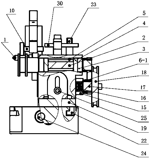
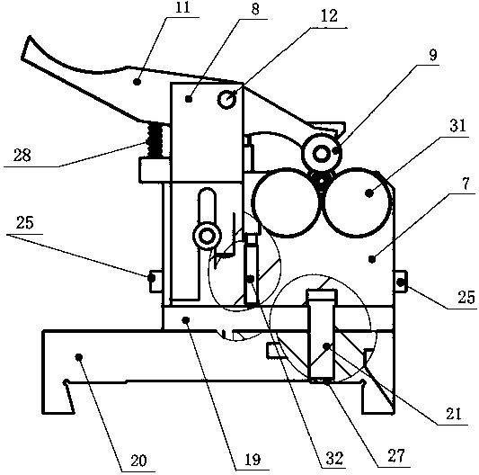
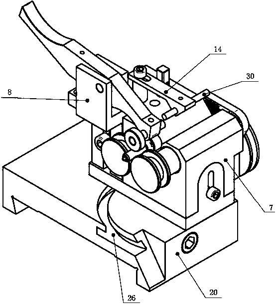
[0023] Refer to attached Figure 1~4 , the transmission mill fixture device includes a large base plate 20, an adjustable base plate 19, a clamp body 7, an adjustment wheel bracket 15, an adjustment wheel shaft 17, a pulley 18, a synchronous wheel 6, a synchronous belt 29, a roller shaft 2, a positioning pin 21, and a locking screw 23, T-shaped locking block 22, pressure wheel support 8, pressure wheel 9, pressure wheel shaft 10, pressure wheel arm 11, spring 28, backing column 13, backing arm 14 and positioning stop pin 30.

[0024] Synchronous wheel 6 is provided with synchronous wheel one 6-1, synchronous wheel two 6-2, synchronous wheel three 6-3.

[0025] The lower part of the large bottom plate 20 is installed on the working table of the cylindrical grinder. The upper part of the large bottom plate 20 is provided with an arc T-shaped slot 26 and a positioning pin hole 27. The T-shaped locking block 22 is installed in the arc T-shaped slot 26. The positioning pin 21 Inst...


PUM


Abstract

The invention relates to a novel transmission grinding clamp device which is a set of processing clamping transmission device used for processing rotation surfaces such as excircles, inner circles and end surfaces of various small slender shaft parts in a choke and pump machining industry by common cylindrical grinding machines, internal grinding machines and surface grinding machines. The transmission grinding clamp device comprises a big bottom plate, an adjustable bottom plate, a clamp body, an adjusting wheel bracket, an adjusting wheel shaft, a belt pulley, synchronizing wheels, a synchronous belt, roller shafts, a positioning pin, a lock screw, a T-shaped lock block, a pinch roller bracket, a pinch roller, a pinch roller shaft, a pinch roller arm, a spring, a backing column, a column, a backing arm and a positioning stop pin; the lower part of the big bottom plate is mounted at a working table of the cylindrical grinding machine; an arc T-shaped groove and a positioning pin hole are formed in the upper part of the big bottom plate; the T-shaped lock block is mounted in the arc T-shaped groove; the positioning pin is mounted in the positioning pin hole; the adjusting bottom plate is mounted at the upper part of the big bottom plate, and connected with the T-shaped lock block and the big bottom plate through the positioning pin and the lock screw.

Description

technical field [0001] The invention relates to a new transmission grinding fixture device, which is a set of ordinary cylindrical grinders, internal grinders, surface grinders, tool grinders, etc. used for machining the outer circles of various slender shafts and small parts in the oil nozzle and oil pump industry. Clamping transmission device for processing rotating surfaces such as inner circles and end faces. Background technique [0002] At present, the transmission grinding fixture device used in the processing of small shaft parts in the oil nozzle and oil pump industry is that the workpiece is installed on the V-shaped bracket, and a driving wheel is used to press the workpiece and drive the workpiece to rotate. The driving wheel is usually a large friction coefficient. Made of rubber, this kind of fixture device, usually a set of fixtures can only be used for the processing of one process, and the clamping height and clamping angle of the workpiece cannot be changed...

Claims


Application Information

Patent Timeline
IPC IPC(8): B24B41/06
CPCB24B41/06
Inventor 王厂贤程诚张先启
Owner JIANGSU FEIFAN INSTR
Learn More