
Solar Cell Electroplating Fixture

A technology of solar cells and electroplating fixtures, applied in circuits, electrolytic processes, electrolytic components, etc., can solve problems affecting the quality of cell electroplating, cells are easy to break, and cell positions are shifted, so as to improve the quality and efficiency of electroplating , reduce the breakage rate, avoid the effect of breakage

Active Publication Date: 2017-01-04
平邑经济开发区投资发展有限公司
View PDF5 Cites 2 Cited by
  • Summary
  • Abstract
  • Description
  • Claims
  • Application Information

AI Technical Summary

Problems solved by technology

[0006] In addition, in the assembly process before the electroplating of the cells, the position of the cells may be shifted. On the one hand, this will cause assembly difficulties, and on the other hand, it will hinder the quality of electroplating.
[0007] In addition, in the process of electroplating the battery, if the clamping force on the battery is too large, the battery is easy to break, and if the clamping force on the battery is too small, it may cause poor electrical contact and affect the electroplating of the battery. quality

Method used


Image

  • Solar Cell Electroplating Fixture
  • Solar Cell Electroplating Fixture
  • Solar Cell Electroplating Fixture

Examples


Embodiment Construction

[0035] Before explaining the technical solutions of the various embodiments of the present invention in detail, the terms and terms involved will be explained. It should be noted that in this specification, components with the same name or the same number represent similar or identical structures, and are for illustrative purposes only.

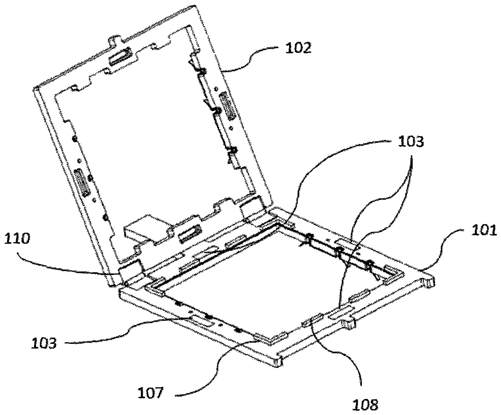
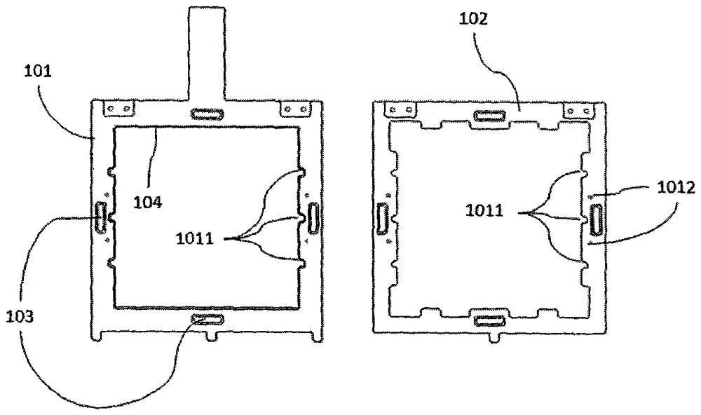
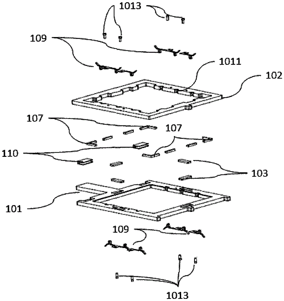
[0036] figure 1 It is a structural schematic diagram of the first embodiment of the solar cell sheet electroplating jig of the present invention. like figure 1 As shown, the solar cell sheet electroplating jig of the present invention includes a first frame 101, a second frame 102 and a plurality of magnets 103; the first frame 101 and the second frame 102 are hollow, and the first frame 101 is in contact with the edge portion of the second frame 102 and clamps the battery sheet; the plurality of magnets 103 are symmetrically fixed on the first frame 101 or the second frame 102 respectively, and the first frame is magnetically 101 is attac...


PUM

PropertyMeasurementUnit
widthaaaaaaaaaa
depthaaaaaaaaaa

Abstract

The invention provides an electroplating clamp of a solar cell. The electroplating clamp of the solar cell, provided by the invention, comprises a first frame, a second frame and a plurality of magnets, wherein the first frame and the second frame are of a hollow shape, edge parts of the first frame and the second frame are in contact and clamp the cell; and the plurality of magnets are respectively symmetrically fixed on the first frame or second frame, and the first frame and the second frame are jointed by using a magnetic force. The electroplating clamp of the solar cell, provided by the invention, is capable of rapidly locating the cell, quick in assembly, and continuous in production, ensures that the cell is uniformly conducted, and is capable of reducing the breakage rate of the cell.

Description

technical field [0001] The invention relates to a solar cell electroplating equipment, in particular to a solar cell sheet electroplating jig. Background technique [0002] In recent years, due to the increasingly severe environmental protection problems, the global energy supply has been showing a tense situation. In this context, new energy technologies, especially solar technology, have developed rapidly. [0003] A solar cell is a device that converts sunlight into electricity. In order to manufacture a solar cell, it is necessary to form a circuit on the cell substrate by electroplating. Electroplating is one of the new technologies that may be adopted in the future in the field of solar cells. During electroplating, it is necessary to put the battery sheet into the electrolyte, and connect the cathode to the battery sheet for electroplating. [0004] Electroplating solar cells requires multiple complex processes. The assembly process before electroplating is very ...

Claims


Application Information

Patent Timeline
Patent Type & Authority Patents(China)
IPC IPC(8): C25D17/08C25D7/12
Inventor 王华刚
Owner 平邑经济开发区投资发展有限公司
Learn More