Safety interlocking device of still kettle door quick to open
A technology of safety interlock device and autoclave, which is applied in the direction of pressure vessels, fixed-capacity gas storage tanks, mechanical equipment, etc., can solve the problems of high maintenance cost, autoclave explosion, damage, etc., and achieve a high degree of automation and extended The effect of service life and stability guarantee
- Summary
- Abstract
- Description
- Claims
- Application Information
AI Technical Summary
Problems solved by technology
Method used
Image

Examples
Embodiment Construction
[0028] The present invention will be further described in detail below in conjunction with the accompanying drawings and specific embodiments.
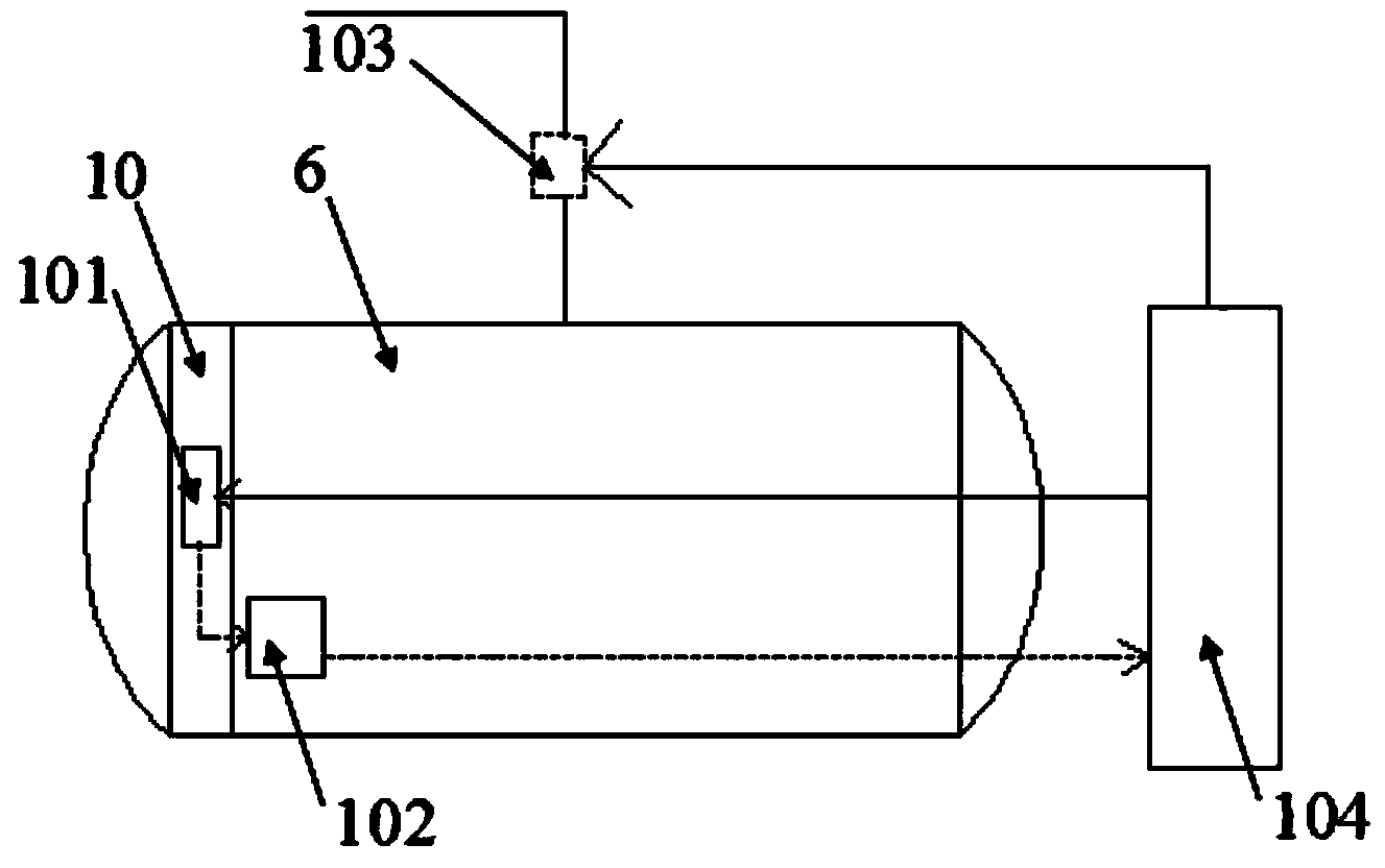
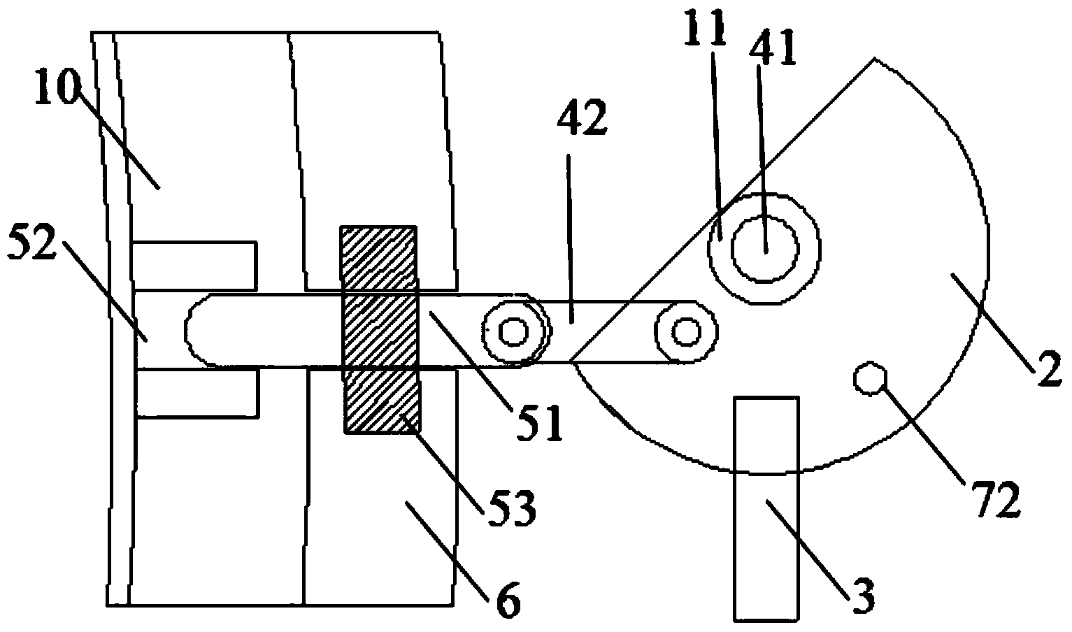
[0029] Such as Figure 1-4 As shown, a quick-opening safety interlock device for an autoclave includes a mechanical locking mechanism 101 and a self-locking mechanism 102. The mechanical locking mechanism includes: a support 1, a semicircular plate 2, a handle 3, and a transmission part 4. bit part 5,
[0030] The support 1 is a flat support with a column, which is fixed on the kettle body 6 in the horizontal direction;
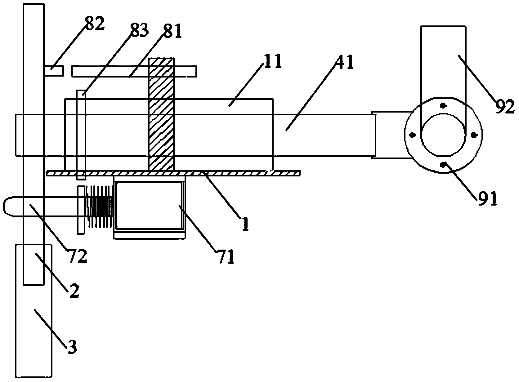
[0031] Transmission part 4 comprises: transmission shaft 41 and connecting rod 42, and transmission shaft 41 is provided with sleeve 11, and sleeve 11 is fixedly connected with bearing 1, and transmission shaft 41 passes through sleeve 11 behind semicircular plate 2 and semicircular plate 2 Fixedly connected, the semicircular plate 2 rotates with the transmission shaft 41 as the rotating shaft, one end of the conne...
PUM
 Abstract
Description
Claims
Application Information
PatSnap Eureka turns technology decisions into work you can execute. Powered by our Innovation Knowledge Graph, it runs expert workflows across engineering, life sciences, materials and intellectual property. Get your review-ready output in minutes.


