Electric energy storage air heater

A technology of hot air blower and induced draft fan, which is applied in the direction of heat storage equipment, electric heating system, space heating and ventilation, etc., and can solve the problems of unfavorable energy storage equipment intensification, modularization, limited pavement height, and complicated construction. Achieve the effect of good heat transfer, simple structure and large energy storage

Inactive Publication Date: 2014-09-10
李渊
View PDF0 Cites 3 Cited by
  • Summary
  • Abstract
  • Description
  • Claims
  • Application Information

AI Technical Summary

Problems solved by technology

[0004] The existing technology has many defects such as complex construction, high cost, and limited pavement height, which is not conducive to the development of energy storage equipment in the direction of intensification and modularization

Method used


Image

  • Electric energy storage air heater
  • Electric energy storage air heater
  • Electric energy storage air heater

Examples


Embodiment 1

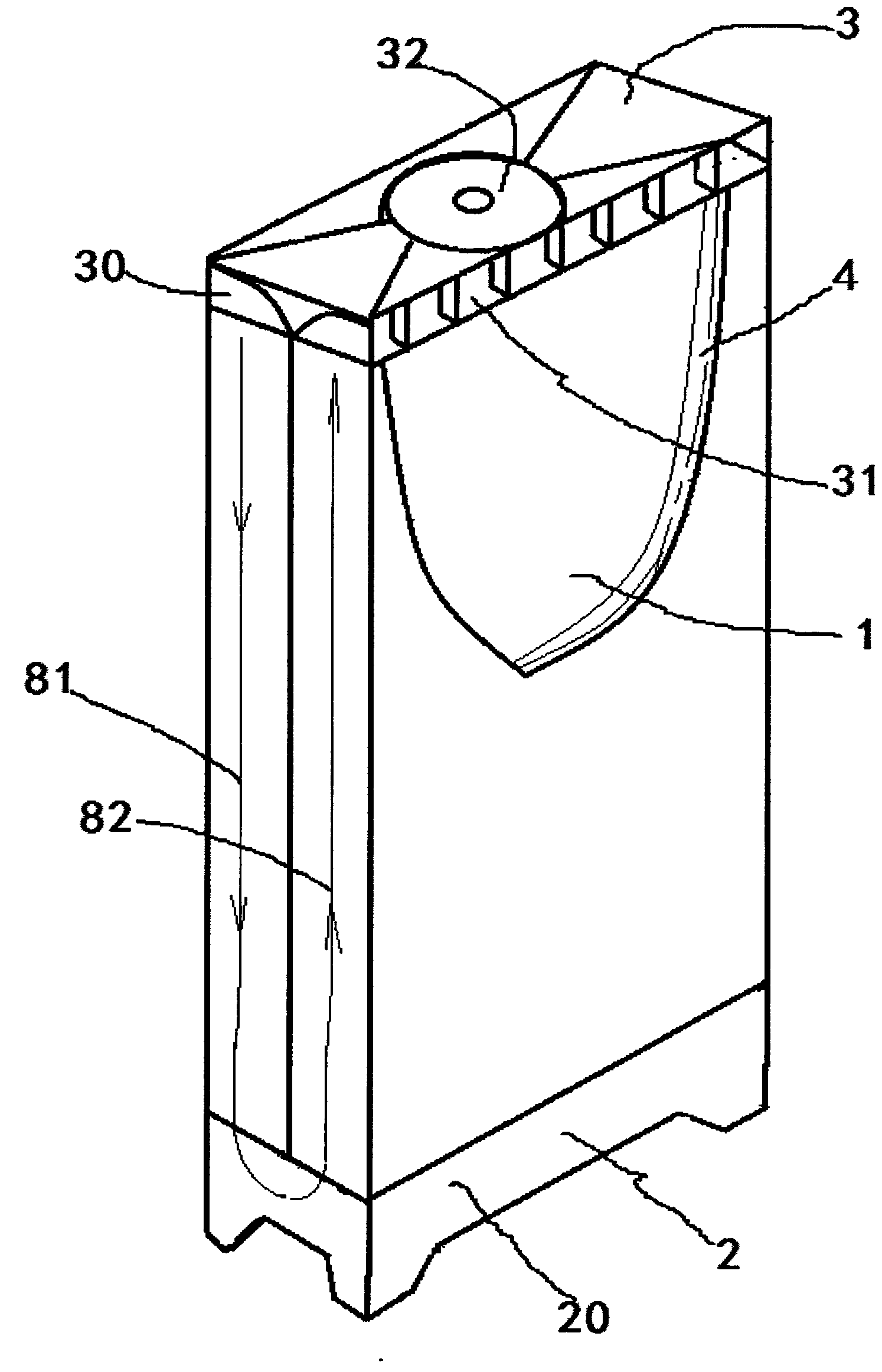
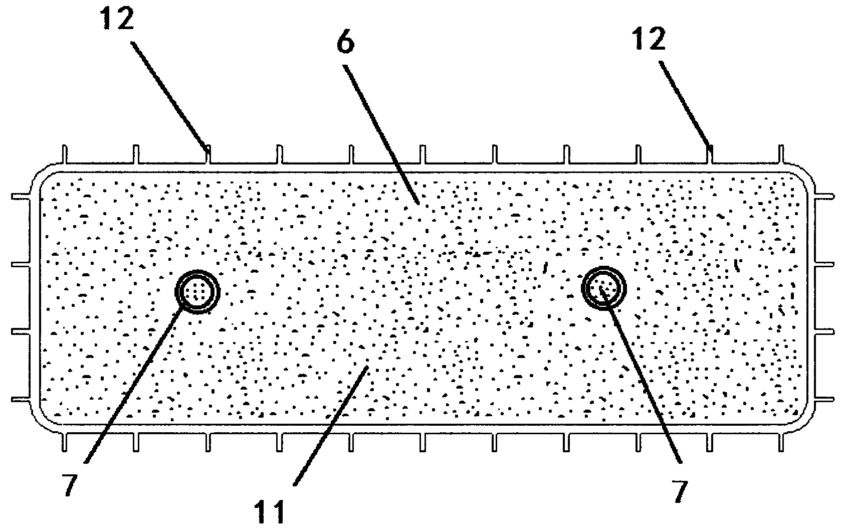
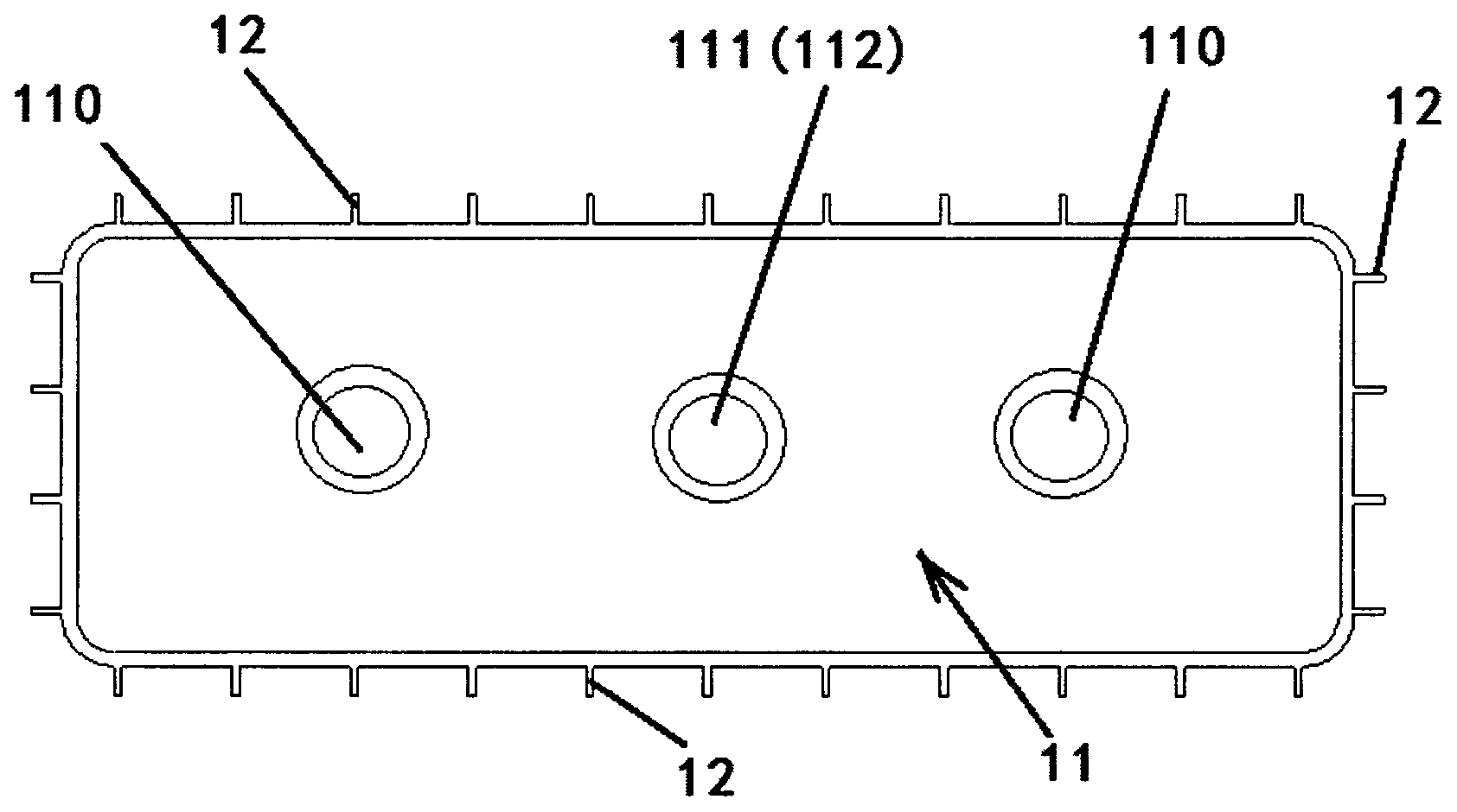
[0032] Such as figure 1 , figure 2 , image 3 , Figure 4 , Figure 5 , Figure 6 , Figure 7 , Figure 8 , Figure 9 As shown, an electric energy storage hot air blower includes several energy storage units 1, a base 2, a top cover 3, a thermal insulation shell 4 and an electrical control system 5, and each energy storage unit 1 is provided with a phase change accumulator Energy material 6 and electric heating element 7.

[0033] Such as figure 2 , image 3 , Figure 4 , Figure 9 As shown, each energy storage cell 1 includes an energy storage cavity 11, and a plurality of heat dissipation strips 12 are arranged on the outer surface of each energy storage cell 1. The energy storage cavity 11 and the heat dissipation strip 12 are integrally structured. An air channel 8 is formed between the energy storage cells 1 and between the energy storage cells 1 and the inner wall of the heat-insulating shell 4, the energy storage cavity 11 is in the shape of a closed conta...

Embodiment 2

[0038] Such as figure 2 , image 3 , Figure 4 , Figure 5 , Figure 6 , Figure 7 , Figure 8 , Figure 9 and Figure 10 As shown, an electric energy storage hot air blower includes several energy storage units 1, a base 2, a top cover 3, a thermal insulation shell 4 and an electrical control system 5, and each energy storage unit 1 is provided with a phase change accumulator Energy material 6 and electric heating element 7.

[0039] Such as figure 2 , image 3 , Figure 4 , Figure 9 As shown, each energy storage cell 1 includes an energy storage cavity 11, and a plurality of heat dissipation strips 12 are arranged on the outer surface of each energy storage cell 1. The energy storage cavity 11 and the heat dissipation strip 12 are integrally structured. An air channel 8 is formed between the energy storage cells 1 and between the energy storage cells 1 and the inner wall of the heat-insulating shell 4, the energy storage cavity 11 is in the shape of a closed c...

Embodiment 3

[0044] Such as figure 2 , image 3 , Figure 4 , Figure 5 , Figure 6 , Figure 7 , Figure 8 , Figure 9 and Figure 11 As shown, an electric energy storage hot air blower includes several energy storage units 1, a base 2, a top cover 3, a thermal insulation shell 4 and an electrical control system 5, and each energy storage unit 1 is provided with a phase change accumulator Energy material 6 and electric heating element 7.

[0045] Such as figure 2 , image 3 , Figure 4 , Figure 9 As shown, each energy storage cell 1 includes an energy storage cavity 11, and a plurality of heat dissipation strips 12 are arranged on the outer surface of each energy storage cell 1. The energy storage cavity 11 and the heat dissipation strip 12 are integrally structured. An air channel 8 is formed between the energy storage cells 1 and between the energy storage cells 1 and the inner wall of the heat-insulating shell 4, the energy storage cavity 11 is in the shape of a closed c...


PUM


Abstract

The invention belongs to the technical field of building energy conservation, relates to indoor heating and energy storage technology, and particularly provides an electric energy storage air heater which is reasonable in design, simple in structure, convenient to mount, good in heat transmission effect, capable of storing energy and high in energy storage capacity. The electric energy storage air heater comprises a plurality of energy storage units, a base, a top cover, a heat insulation shell and an electrical control system, and is characterized in that a phase change energy storage material and an electric heating element are arranged in each energy storage unit. The electric energy storage air heater has promising application in the fields of solar energy utilization, 'peak load shifting' of electric power, recovery of waste heat and excess heat, energy conservation of industrial and civil buildings and air conditioners, and the like.

Description

technical field [0001] The invention belongs to the technical field of heating, ventilation and building energy saving, and relates to an electric energy storage hot air blower for indoor heating and energy storage technology. Background technique [0002] With the improvement of people's living standards and the comfort of working and living environments, the energy consumption of air conditioners has increased significantly, resulting in excessive energy consumption, increased environmental pollution, excessive peak and valley loads on the power grid, and serious shortage of power supply during peak loads. Such as the increase of building energy consumption. At present, the building energy consumption in developed countries in Europe and the United States has reached 40% of the total energy consumption of the whole society. In my country, building energy consumption accounts for about 30% of the total energy consumption in the country. With the continuous development of the ...

Claims


Application Information

Patent Timeline
Patent Type & Authority Applications(China)
IPC IPC(8): F24D13/00F28D20/02
CPCY02E60/145Y02E60/14
Inventor 李渊李增清
Owner 李渊
Why Eureka
Try Eureka