
Elastic anisotropic metal matrix thermal barrier coating thickness ultrasonic measurement method

A metal matrix, anisotropic technology, applied in measurement devices, using ultrasonic/sonic/infrasonic waves, instruments, etc., can solve problems such as main frequency offset, waveform distortion, inaccurate measurement of thermal barrier coating thickness, etc. Low requirements, low cost, and the effect of solving the large error of coating ultrasonic thickness measurement results

Active Publication Date: 2014-09-10
DALIAN UNIV OF TECH
View PDF4 Cites 14 Cited by
  • Summary
  • Abstract
  • Description
  • Claims
  • Application Information

AI Technical Summary

Problems solved by technology

However, for thermal barrier coating samples on metal substrates represented by nickel-based superalloys, due to the dendrite segregation and recrystallization of the substrate during the preparation process, resulting in elastic anisotropy, ultrasonic waves will Cause waveform distortion and main frequency shift and other phenomena, and then cause thermal barrier coating thickness measurement inaccurate
None of the above methods can effectively solve the problem of non-destructive measurement of the thickness of thermal barrier coatings on elastic anisotropic metal substrates.

Method used


Image

  • Elastic anisotropic metal matrix thermal barrier coating thickness ultrasonic measurement method
  • Elastic anisotropic metal matrix thermal barrier coating thickness ultrasonic measurement method
  • Elastic anisotropic metal matrix thermal barrier coating thickness ultrasonic measurement method

Examples


Embodiment Construction

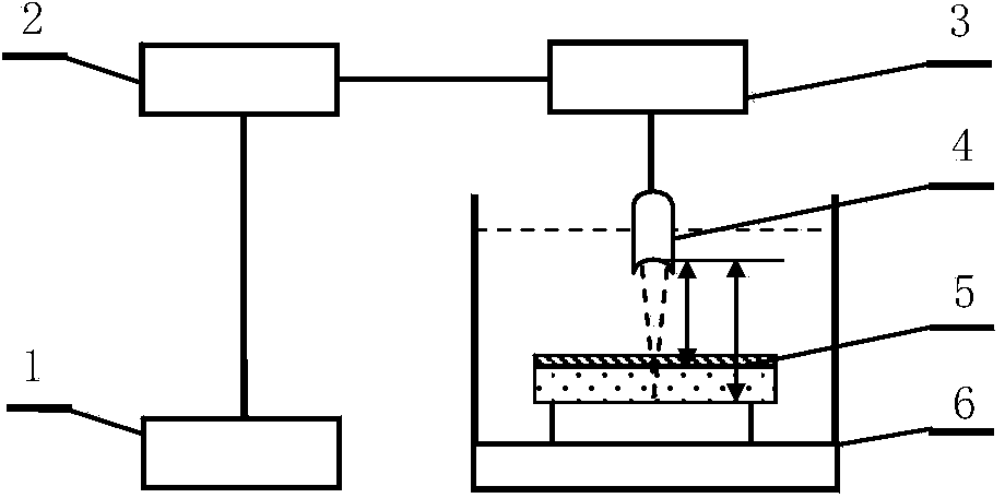
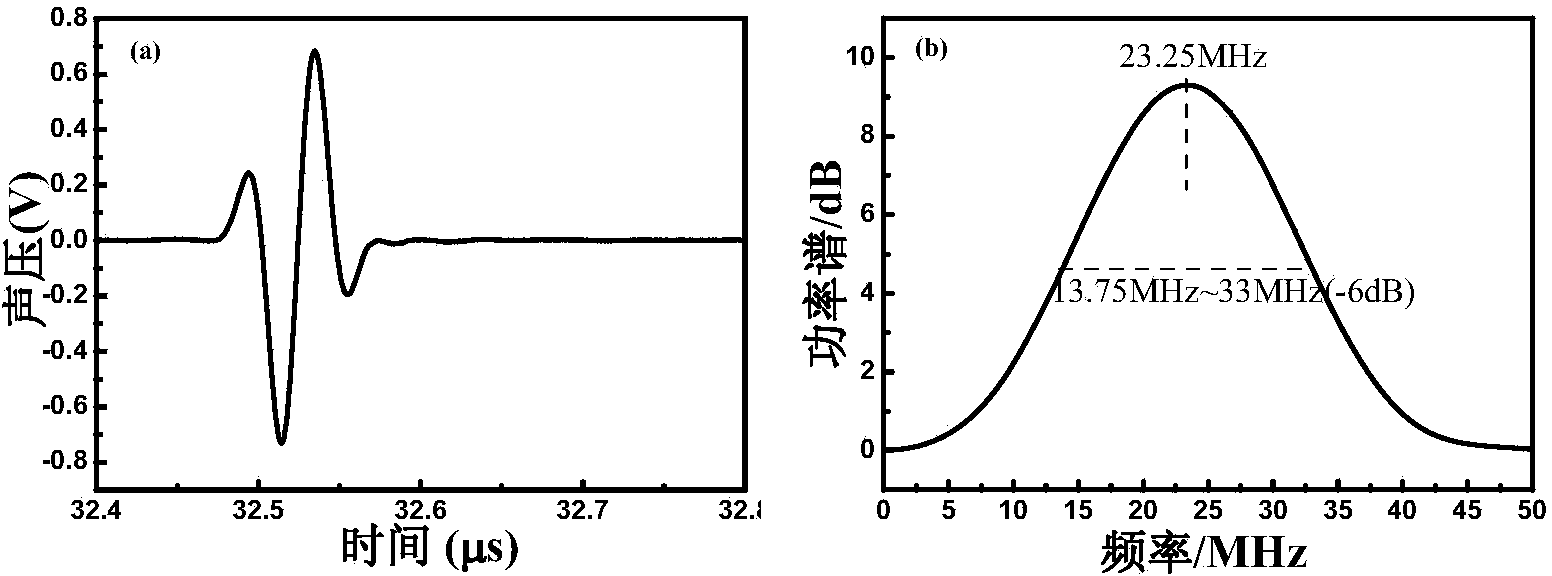
[0031] The ultrasonic measurement method for the thickness of thermal barrier coatings on elastic anisotropic metal substrates adopts figure 1 The ultrasonic pulse echo method C-scan thickness measurement system shown is composed of a SM-J38-300 ultrasonic C-scan device, a nominal 25MHz water immersion point focusing probe, a DPO4O32 digital oscilloscope and a computer. The nominal 60 μm thick nickel-based superalloy substrate YSZ coating sample, the uniform stainless steel substrate YSZ coating sample with a coating thickness of 40-120 μm, and the nickel-based superalloy substrate sample were measured respectively. The measurement steps used are as follows :

[0032] (1) Calibrate the ultrasonic pulse echo method C-scan thickness measurement system, place the nominal 25MHz water immersion point focusing probe above the nickel-based superalloy substrate sample, adjust the water immersion focusing probe so that the axis of the main sound beam is in line with the surface of the ...


PUM


Abstract

An elastic anisotropic metal matrix thermal barrier coating thickness ultrasonic measurement method belongs to the technical field of ultrasonic nondestructive testing. The elastic anisotropic metal matrix thermal barrier coating thickness ultrasonic measurement method achieves measurement of samples to be tested and reference samples through an ultrasonic pulse echo method C-scan thickness measuring system composed of an ultrasonic C-scan device, a water penetration focusing probe, a digital oscilloscope and a computer and comprises, for elastic anisotropic metal matrix thermal barrier coating sample ultrasonic echo signals, extracting all the delta gamma & gt: 0 in the elastic anisotropic metal matrix thermal barrier coating sample ultrasonic echo signals through a defined correction factor delta gamma, computing the normalization power spectrum Gm (f) of the elastic anisotropic metal matrix thermal barrier coating sample ultrasonic echo signals, reading the resonant frequency fn in the effective frequency band of the Gm (f), and substituting a known thermal barrier coating longitudinal wave velocity c into a sound pressure reflection factor power spectrum resonant frequency expression to achieve elastic anisotropic metal matrix thermal barrier coating thickness measurement. The elastic anisotropic metal matrix thermal barrier coating thickness ultrasonic measurement method effectively overcomes the problem that ultrasonic waveform distortion and dominant frequency migration due to elastic anisotropy of a matrix results in large errors of thermal barrier coating thickness measurement results.

Description

technical field [0001] The invention relates to an ultrasonic measurement method for the thickness of a thermal barrier coating on an elastic anisotropic metal substrate, which belongs to the technical field of ultrasonic nondestructive testing. Background technique [0002] Using thermal barrier coatings to increase the operating temperature of engine blades and other hot-end components is a very economical and effective technical approach, and the thickness and uniformity of thermal barrier coatings directly affect the final heat insulation effect. In the process of on-site coating construction and quality inspection, the thickness of the sprayed thermal barrier coating is required to meet the qualified standard. An accurate and reliable non-destructive testing method for the thickness of thermal barrier coatings is an urgent engineering demand in this field. [0003] A variety of non-destructive testing methods can be used to measure the thickness of thermal barrier coat...

Claims


Application Information

Patent Timeline
IPC IPC(8): G01B17/02
Inventor 林莉马志远罗忠兵李广凯赵灿雷明凯
Owner DALIAN UNIV OF TECH
Learn More