Integrated multi-waveband common-path synchronous continuous variable-focus optical system

An optical system and common optical path technology, applied in optics, optical components, instruments, etc., can solve problems such as reducing the real-time performance and response speed of the system, inability to accurately track and measure targets, and different zoom ranges and focal lengths. Subsequent control circuit and mechanical clamping structure are beneficial to system processing and small volume.

Active Publication Date: 2014-09-10
XIAN TECH UNIV
View PDF4 Cites 23 Cited by
  • Summary
  • Abstract
  • Description
  • Claims
  • Application Information

AI Technical Summary

Problems solved by technology

[0003] At present, the different band systems of the multi-band zoom optical system are designed separately, and then clamped together to form a multi-band optical system. Specifically, the visible, medium-wave and long-wave infrared optical systems are three separate components of the visible system and the medium-wave and long-wave infrared systems. The combination of the system results in a relatively large system volume
Because the existing multi-band zoom optical system does not lock the target simultaneously and synchronously in different bands, after the optical path is switched, it is necessary to search for the target again until the target is found, and then adjust the focal length to observe the target again. The optical path switching process takes a long time, greatly reducing the system real-time and response speed, when the target being tracked and measured is moving fast, the target may be lost
In addition, the zoom range and focal length are different between different bands of the system. When the light is switched, it is likely to exceed the observation distance and cannot accurately track and measure the target

Method used


Image

  • Integrated multi-waveband common-path synchronous continuous variable-focus optical system
  • Integrated multi-waveband common-path synchronous continuous variable-focus optical system
  • Integrated multi-waveband common-path synchronous continuous variable-focus optical system

Examples


Embodiment Construction

[0022] The present invention will be described in detail below in conjunction with the accompanying drawings.

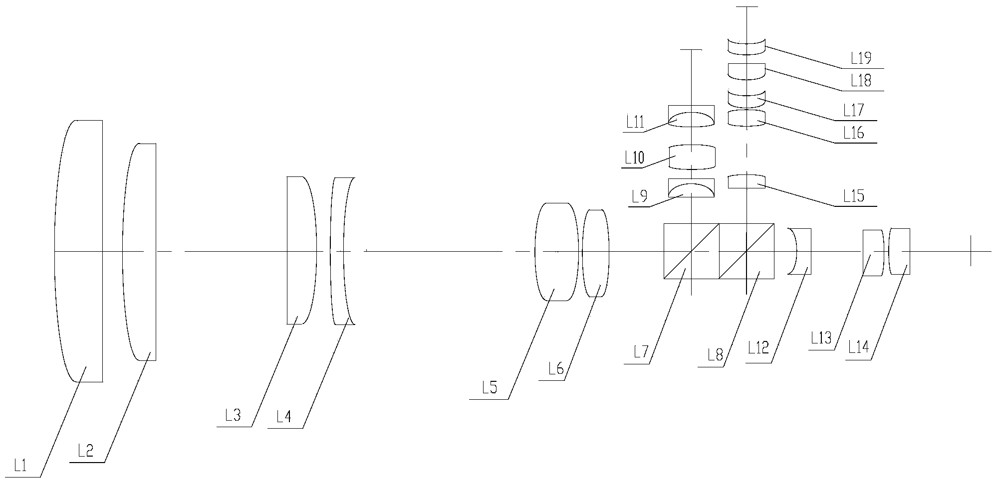
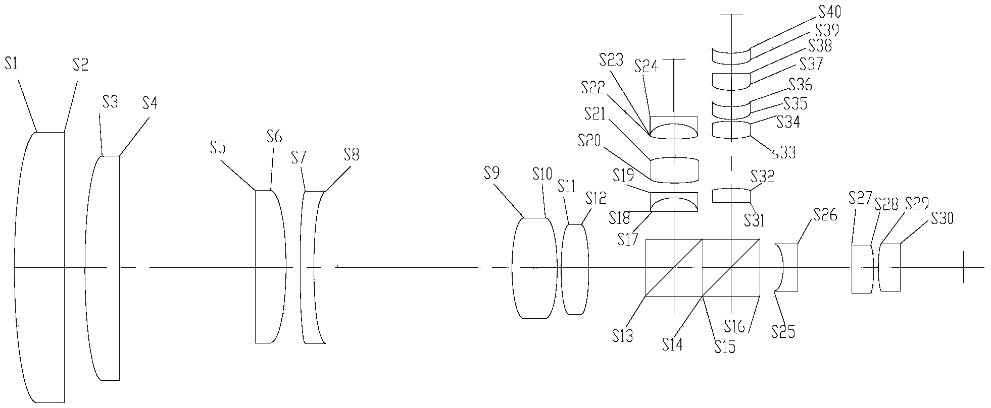
[0023] see figure 1 , the present invention includes the common front fixed group, the public variable power group, the public compensation group arranged in sequence along the optical axis, and the first group of optical prisms L7 for reflecting visible light, transmitting mid-wave infrared light and long-wave infrared light, and for reflecting long-wave Infrared light, the second component light prism L8 that transmits mid-wave infrared light; the reflection light path of the first component light prism L7 is provided with a visible light rear fixing group, and the transmission light path of the second component light prism L8 is provided with a mid-wave infrared light rear The fixed group, the second group of light prism L8 is provided with long-wave infrared light on the reflected light path and then the fixed group. Both the first component light prism L7 and t...


PUM


Abstract

The invention discloses an integrated multi-waveband common-path synchronous continuous variable-focus optical system. The optical system comprises a public front fixed group, a public zooming group and a public compensation group which are arranged in sequence along an optical axis, as well as a first group of beam splitter prisms for reflecting visible light and transmitting medium-wave infrared light and long-wave infrared light, and a second group of beam splitter prisms for reflecting long-wave infrared light and transmitting medium-wave infrared light. A common-caliber, common-path and common-variable-focus form is adopted, a visible waveband, a medium-wave waveband and a long-wave infrared waveband are zoomed synchronously and continuously along with the movement of the public zooming group in a zooming process, and the three wavebands are of the same focal lengths, zooming ratios and visual fields, thereby realizing synchronous observation, synchronous tracking and synchronous measurement of a target in the visible waveband, the medium-wave waveband and the long-wave infrared waveband. When different wavebands are needed for observing, path switching and new search of the target are unnecessary, thereby increasing the reaction speed of the optical system and preventing loss of a target moving at a high speed during path switching.

Description

technical field [0001] The invention belongs to the technical field of optical equipment, and in particular relates to an integrated multi-band common optical path synchronous continuous zoom optical system. Background technique [0002] With the continuous application in the field of industrial detection and security reconnaissance and the increasingly complex application environment, higher and higher requirements are put forward for the miniaturization, light weight, response speed and real-time performance of the imaging optical system. In this context, a zoom optical system with multiple wavelength bands integrated came into being. The zoom system can quickly search and find targets at short focus and large field of view, accurately observe and measure targets at long focus and small field of view, and can track and lock targets in real time by continuously changing the focal length. Multi-band optical system has become an important direction in the development of toda...

Claims


Application Information

Patent Timeline
Patent Type & Authority Applications(China)
IPC IPC(8): G02B15/163
Inventor 高明刘钧吕宏陈阳巩蕾
Owner XIAN TECH UNIV
Why Eureka
Try Eureka